
Method for determination of fuselage shape of supersonic aircraft, and fuselage front section shape

a supersonic aircraft and fuselage technology, applied in the direction of fuselages, airflow influencers, transportation and packaging, etc., can solve the problems of limited supersonic flight, difficult commercialization of supersonic passenger aircraft, and considerable airframe drag, so as to reduce the suppress the increase in wave drag, and reduce the effect of overall airframe wave drag

Active Publication Date: 2007-12-18
JAPAN AEROSPACE EXPLORATION AGENCY
View PDF2 Cites 12 Cited by
  • Summary
  • Abstract
  • Description
  • Claims
  • Application Information

AI Technical Summary

Benefits of technology

The patent describes a method for designing the shape of an advanced supersonic aircraft's fuselage to reduce sonic boom and wave drag. The method involves determining the upper and lower surface shapes of the fuselage by optimizing objective functions to minimize pressure increase and drag. The resulting front section shape of the aircraft is designed to suppress sonic boom and shock waves, and to create a gradual pressure increase from the nose to the rear of the nose. This design method can lead to more efficient use of the Area Rule design, which is a popular method for reducing wave drag. Overall, the patent provides a technical solution for creating a supersonic aircraft with a unique fuselage shape that reduces sonic boom and wave drag.

Problems solved by technology

Because supersonic flight is limited in airspace over terrain where noise due to sonic boom is a problem, commercialization of supersonic passenger aircraft has been difficult.
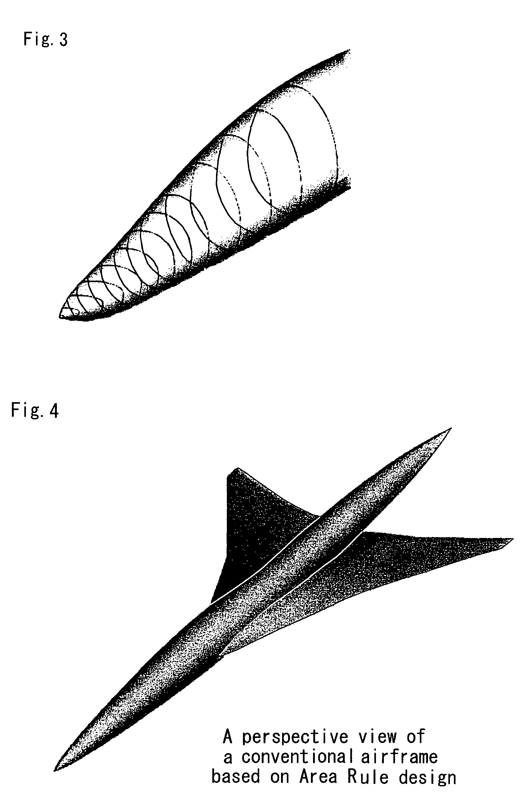
However, if a shape having such an equivalent cross-sectional area distribution is computed, the nose shape is blunt, resulting in considerable airframe drag.
However, such a blunt nose shape cannot satisfy the [conditions of the] above-described Area Rule design to minimize wave drag, and an increase in wave drag is unavoidable.
Thus there has not yet been found an ideal aircraft shape which achieves [the aims of] both the Area Rule design, and low sonic boom design.

Method used


Image

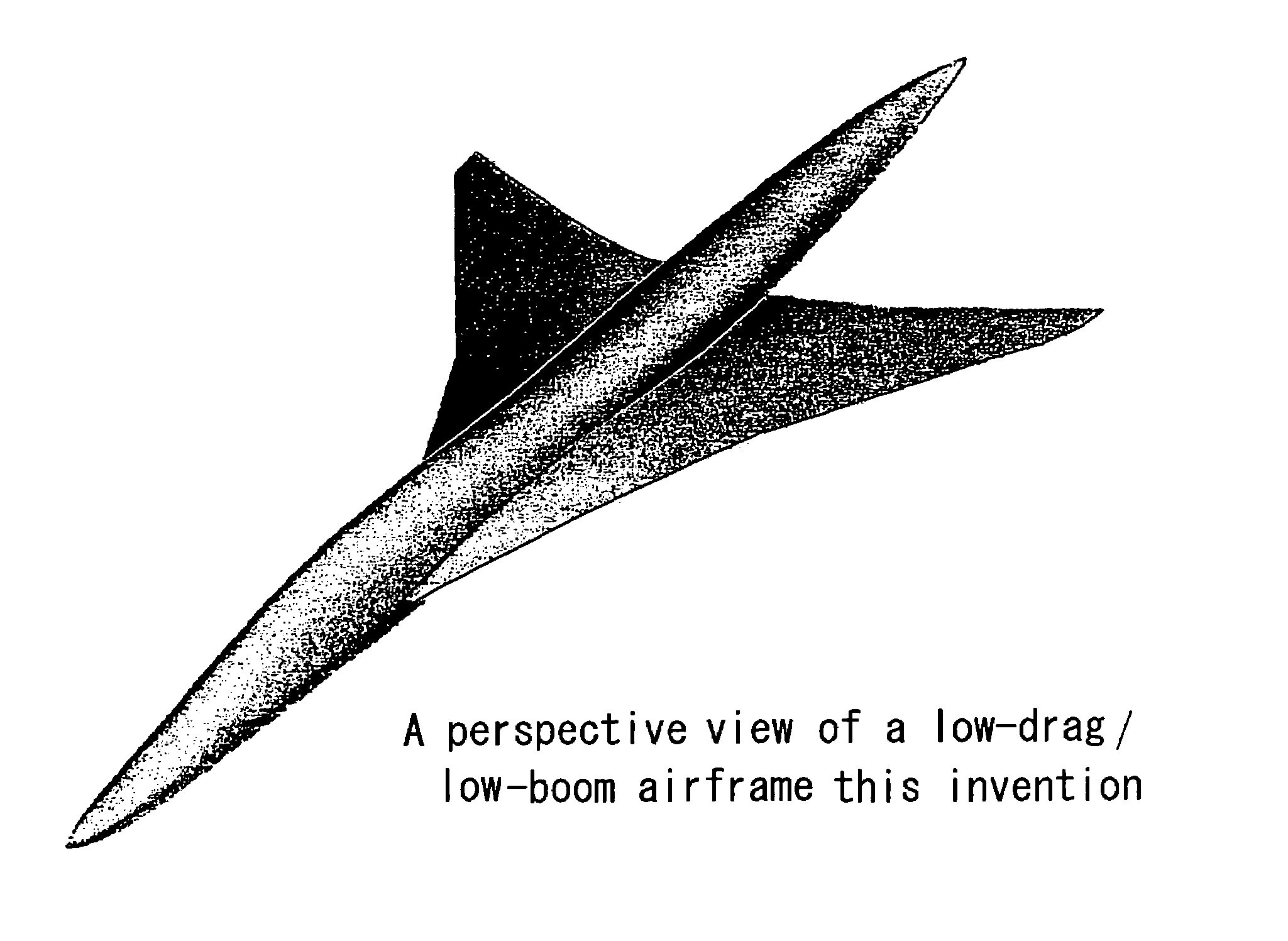
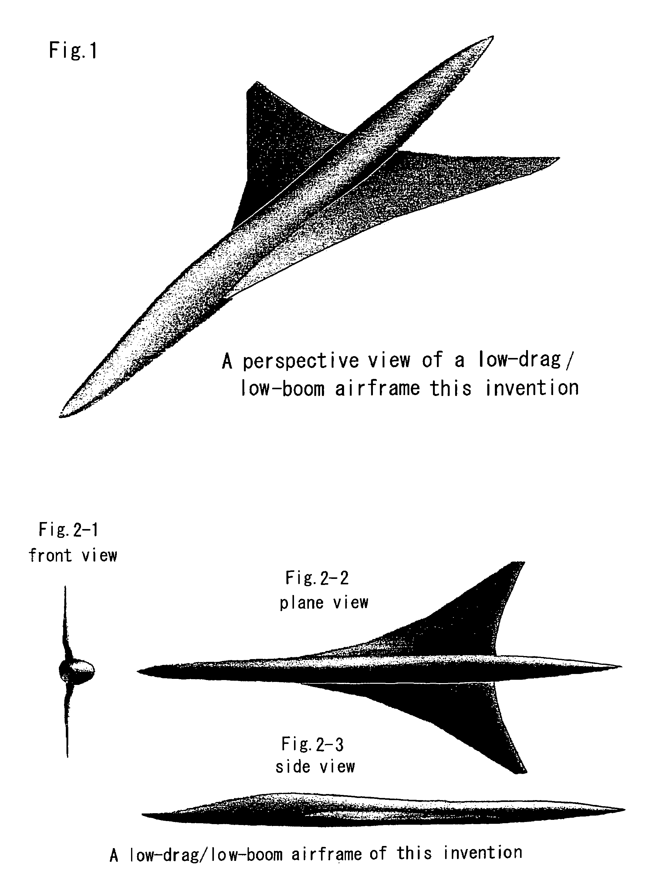
  • Method for determination of fuselage shape of supersonic aircraft, and fuselage front section shape
  • Method for determination of fuselage shape of supersonic aircraft, and fuselage front section shape
  • Method for determination of fuselage shape of supersonic aircraft, and fuselage front section shape

Examples


embodiment 1

[0039]An embodiment of the invention is described. Different methods are used to determine the fuselage lower-surface shape and the fuselage upper-surface shape, whose upper and lower boundary is defined for each fuselage cross-section by the horizontal line including two points at which the fuselage width from the bilateral symmetry plane is maximum. The upper cross-sectional shape of the fuselage front section, from the fuselage tip to the wing-fuselage juncture, is taken to be a semi-ellipse; the lower-surface shape is taken to be a semicircle of radius equal to the radius in the side directions of the above cross-sectional shape. As shown in FIG. 6, the fuselage shape from the fuselage tip to the wing-fuselage juncture (X=0 to L1), taking the axial direction length of the fuselage to be L, is determined as follows. In the following, the axial direction coordinate X is expressed by a dimensionless coordinate (x=X / L1), and as shown in FIG. 7, at the position at which X=L1, that is...


PUM


Abstract

Objectives to be achieved by this invention are the provision of a method for determining the ultimate fuselage shape of supersonic aircraft by integral modification of the upper and lower surface shapes of the fuselage, to reduce sonic boom without increasing wave drag, as well as the provision of such a fuselage front section shape. A method for determining the fuselage shape of an aircraft for supersonic flight of this invention employs different methods of determining the fuselage lower-surface shape and the fuselage upper-surface shape, whose upper and lower boundary is defined for each fuselage cross-section by the horizontal line including two points at which the fuselage width from the bilateral symmetry plane is maximum. The above fuselage lower-surface shape is determined by optimization of an objective function to minimize the pressure increase amount of the sonic boom pressure waveform on the ground, estimated using a panel method and waveform parameter method; the fuselage upper-surface shape is determined by optimization of an objective function so as to minimize drag, estimated using a panel method.

Description

BACKGROUND OF THE INVENTION[0001]1. Field of the Invention[0002]This invention relates to a method of determination of fuselage shape, and a fuselage front section shape, to suppress sonic boom without increasing the wave drag of supersonic aircraft.[0003]2. Description of the Related Art[0004]In general, in order to satisfy conditions for economy and environmental compatibility, a supersonic aircraft must [be designed] so as to suppress wave drag caused by shock waves and sonic boom, which is an acoustic phenomenon affecting persons, animals, buildings and other structures on the ground.[0005]The axisymmetric shape in which the area cross-sectional distribution with respect to the length position is longitudinally symmetric (a Sears-Haack body; see Sears, W. R., “On Projectiles of Minimum Wave Drag”, Quart. Appl. Math., Vol. 14, 1947), shown in FIG. 12, is known as the shape of a body in supersonic flight with minimum wave drag. In order to reduce wave drag of an supersonic aircraf...

Claims


Application Information

Patent Timeline
Patent Type & Authority Patents(United States)
IPC IPC(8): B64C1/38B64C23/00B64C30/00
CPCB64C30/00Y02T50/12B64C2001/0045Y02T50/10
Inventor MAKINO, YOSHIKAZU
Owner JAPAN AEROSPACE EXPLORATION AGENCY
Learn More