Dual pedestal shut-off valve

a shut-off valve and double-peg technology, applied in the direction of valve operating means/releasing devices, mechanical equipment, transportation and packaging, etc., can solve the problems of no longer being able to assume actuation positions and the membrane is stiffened, and achieve the effect of preventing alternate flexure modes of the membrane and gaining a greater latitude in the placement of the first pedestal

Active Publication Date: 2007-12-18
SMC CORP
View PDF18 Cites 2 Cited by
  • Summary
  • Abstract
  • Description
  • Claims
  • Application Information

AI Technical Summary

Benefits of technology

[0007]In the present invention, the valve is configured as a normally closed valve with at least two pedestals, one in the position as described in U.S. Pat. No. 5,865,417 and one approximately 1 mm from the original pedestal toward the far cavity wall, as shown in FIG. 3. The advantages of the current invention over the previous embodiment are several. First, the membrane is stiffened and no longer can assume actuated positions which do not open the cantilever. Second, more force can now be transferred from the actuation mechanism to open the cantilever; this result further allows the line pressure to be increased to over 100 psig and the inlet ports expanded to at least 1 mm in diameter. Third, by stiffening the membrane and preventing alternate flexure modes of the membrane, greater latitude in placement of the first pedestal is gained. This latitude allows the pedestal, acting as the pivot point on the cantilever, to be moved further from the inlet port, thus moving the cantilever further from the inlet port and decreasing the cantilever acting as a restriction in the flow path.
[0008]In some embodiments of the present invention sensing devices are integrated with the valves. In some embodiments these sensing devices are pressure sensors, while in other embodiments these sensing devices are temperature sensors or both. Thus where valves in accordance with embodiments of the present invention have integrated sensing devices to provide dynamic feedback to the energy input source of the energy conversion block, these valves can provide feedback signals to facilitate the control of fluid flow or pressure.

Problems solved by technology

First, the membrane is stiffened and no longer can assume actuated positions which do not open the cantilever.

Method used


Image

  • Dual pedestal shut-off valve
  • Dual pedestal shut-off valve
  • Dual pedestal shut-off valve

Examples


Embodiment Construction

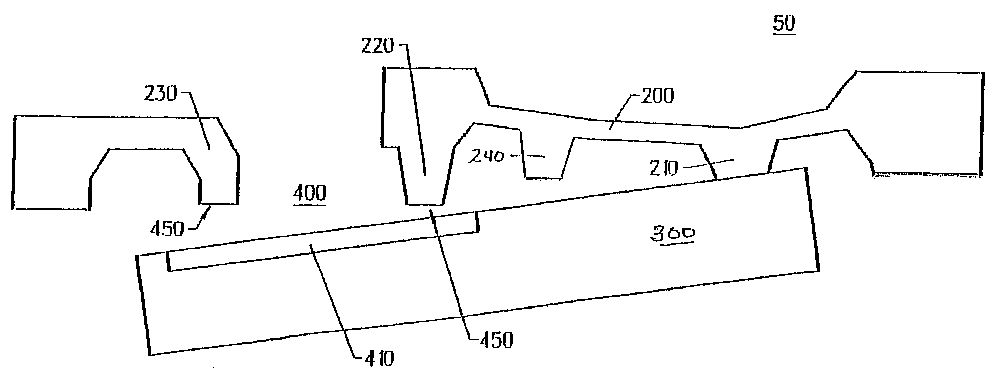
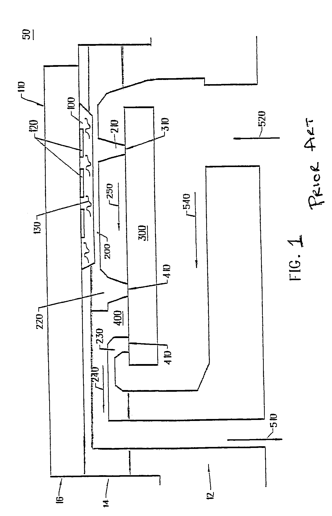
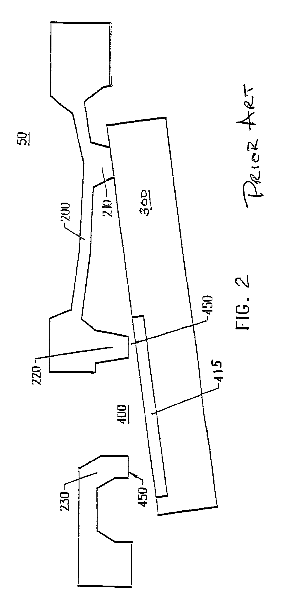
[0015]Embodiments of the present invention will be described with reference to the aforementioned figures. These drawings are simplified for ease of understanding and description of embodiments of the present invention only. Various modifications or adaptations of the specific methods and or structures that represent embodiments of the present invention may become apparent to those skilled in the art as these embodiments are described. All such modifications, adaptations or variations that rely upon the teachings of the present invention, and through which these teachings have advanced the art, are considered to be within the spirit and scope of the present invention. For example, in some embodiments of the present invention, a valve with a single valve port is employed whereas in other embodiments multiple valve ports can be employed. Details of processes that may be used to fabricate portions of embodiments of integrated valve structures is generally known to those of ordinary ski...


PUM


Abstract

Integrated micro-valve is formed to control fluid flow and pressure. The valve converts supplied energy to mechanical energy through a means for energy conversion resident above a flexible wall or membrane. In one embodiment a sealed cavity contains a fluid that expands and contracts as it is heated or cooled, thus causing the flexible wall to move. Movement of this wall or membrane is used to move a valve element and dynamically control the opening or closing of a valve port over a predetermined range. Additional means for stiffening are added to the membrane to improve performance.

Description

FIELD OF THE INVENTION[0001]The invention pertains to the field of integrated, electrically operable micro-valves and, more particularly, to the field of low leak rate integrated micro-valves for industrial, corrosive and ultra-clean applications.BACKGROUND OF THE INVENTION[0002]Micromachined integrated valves are known in the prior art. Examples of various embodiments of such normally open valves are given in U.S. Pat. Nos. 4,821,997 and 4,824,073 and 4,943,032 and 4,966,646; the disclosures of which are hereby incorporated by reference herein in their entirety.[0003]U.S. Pat. Nos. 5,865,417 and 6,149,123 taught how to make a normally closed, micro-machined valve with a leak rate on the order of 1×10⁻⁹ scc-atm / sec or less of helium. U.S. Pat. No. 6,160,243 disclosed alternative methods of actuating micro-valves. U.S. Pat. Nos. 5,865,417 and 6,149,123 and 6,160,243 are included by reference herein in their entirety.[0004]An integrated micro-valve, also commonly referred to as a micr...

Claims


Application Information

Patent Timeline
Patent Type & Authority Patents(United States)
IPC IPC(8): F16K31/02F15C5/00G05D7/06
CPCF15C5/00Y10T137/7761
Inventor HARRIS, JAMES M.SELSER, MICHAELCOZAD, BRADFORD A.HENNING, ALBERT K.
Owner SMC CORP
Why Eureka
Try Eureka