Damper mechanism

a technology of adamper mechanism and a spring, which is applied in the direction of mechanical actuator clutches, couplings, mechanical apparatus, etc., can solve the problems of large coil springs, limited coil spring layout, and inability to adapt to greater variation in torsional characteristics, etc., and achieves the effect of simple structur

Active Publication Date: 2010-07-15
EXEDY CORP
View PDF9 Cites 6 Cited by
  • Summary
  • Abstract
  • Description
  • Claims
  • Application Information

AI Technical Summary

Benefits of technology

[0009]With this damper mechanism, a stopper mechanism is realized by a plurality of linking components that links the pair of input plates. More specifically, the linking components are flat portions formed integrally with one of the input plates. The linking components each have a contact component that extends in the axial direction from the outer peripheral edge of one of the input plates toward the other input plate, and a fixed component that extends inward in the radial direction from the end of the contact component and is fixed to the other input plate. Also, the outer peripheral part of the hub flange is provided with a plurality of protrusions extending outward in the radial direction, and cut-outs formed between the protrusions in the rotational direction. The contact components of the linking components pass through the cut-outs in the axial direction, and come into contact with the protrusions in the rotational direction when the input plates and the hub flange rotate relative to one another. Therefore, with this damper mechanism, no stop pin is used, and a stopper mechanism can be realized by a simple structure.
[0011]Meanwhile, when lower cost is taken into account, there is a need for a damper mechanism with which various torsional characteristics can be obtained while keeping changes to the structure to a minimum.
[0012]It is an object of the present invention to afford greater latitude in the design of a damper mechanism while still keeping changes in the structure to a minimum.
[0015]In this case, since the plurality of linking components are disposed so that the adjacent pitches are different, the size of the elastic members disposed between the linking components can be varied. For instance, elastic members of large size can be disposed in a region of large pitch. As a result, greater variation in the layout and type of elastic members is possible while changes to the structure can be kept to a minimum, so greater variation in the torsional characteristics of the damper mechanism can be attained. Specifically, with this damper mechanism, greater latitude in the design can be obtained while still keeping changes in the structure to a minimum.
[0019]In this case, windows that are larger than in the past can be formed in the region of the linking components where the adjacent pitches are larger. As a result, elastic members that are larger than those in the past can be disposed, which makes it easier to increase variations in the torsional characteristics.
[0022]In this case, the distance between adjacent protrusions can be increased, and the relative rotational angle between the first rotary members and the second rotary member can also be increased. That is, with this damper mechanism, an operating angle that is the same or larger than that in the past can be ensured.

Problems solved by technology

In other words, with this damper mechanism, even though some of the coil springs can be made smaller, making some of the coil springs larger is extremely difficult in terms of layout.
That is, with a conventional damper mechanism, the layout of the coil springs tends to be limited, and the structure does not lend itself to greater variation in torsional characteristics.

Method used


Image

  • Damper mechanism
  • Damper mechanism
  • Damper mechanism

Examples


Embodiment Construction

[0036]An embodiment of the damper mechanism pertaining to the present invention will now be described through reference to the drawings. The example described here is of a clutch disk assembly in which a damper mechanism is installed.

1. Overall Configuration of Clutch Disk Assembly

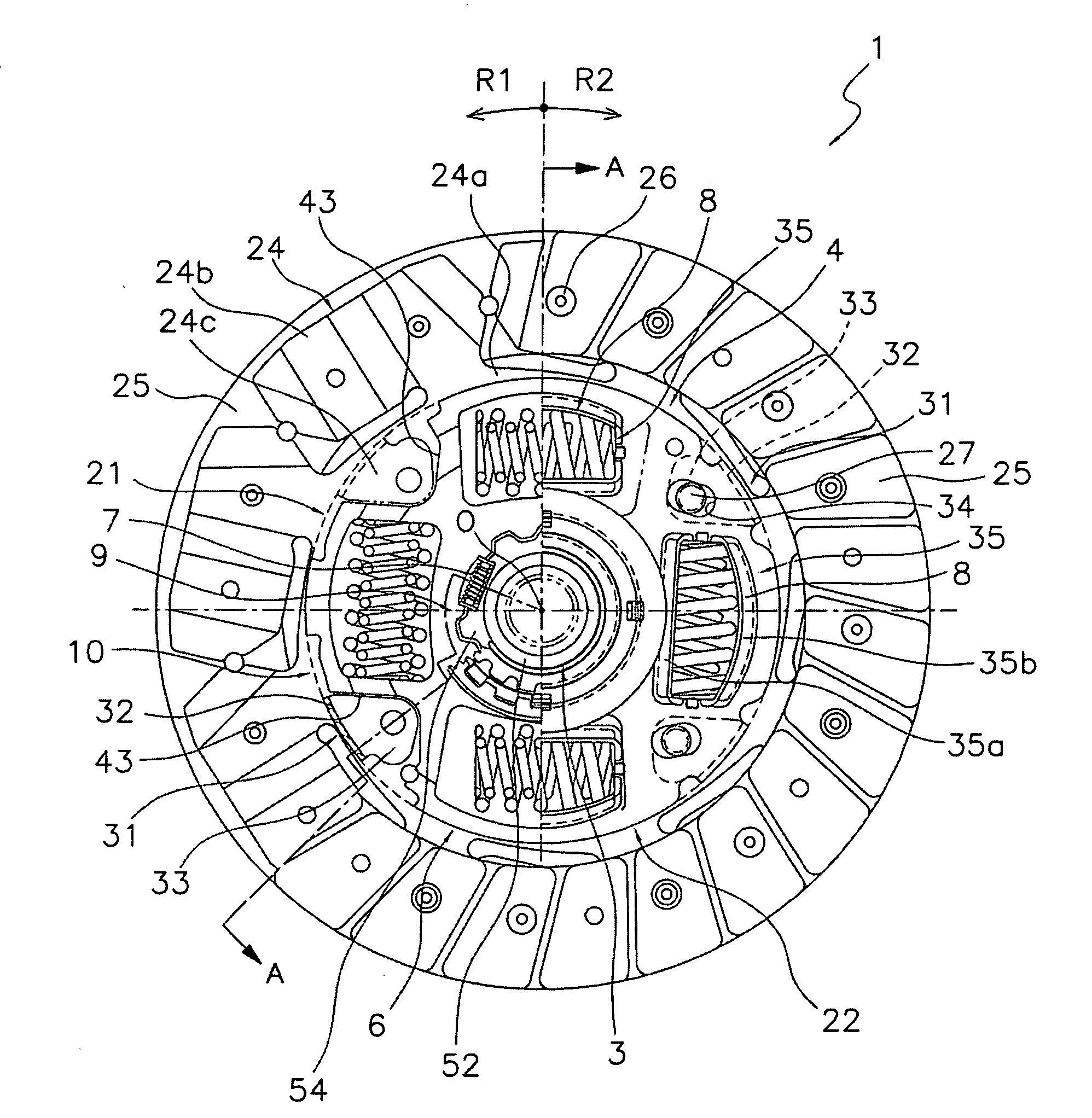
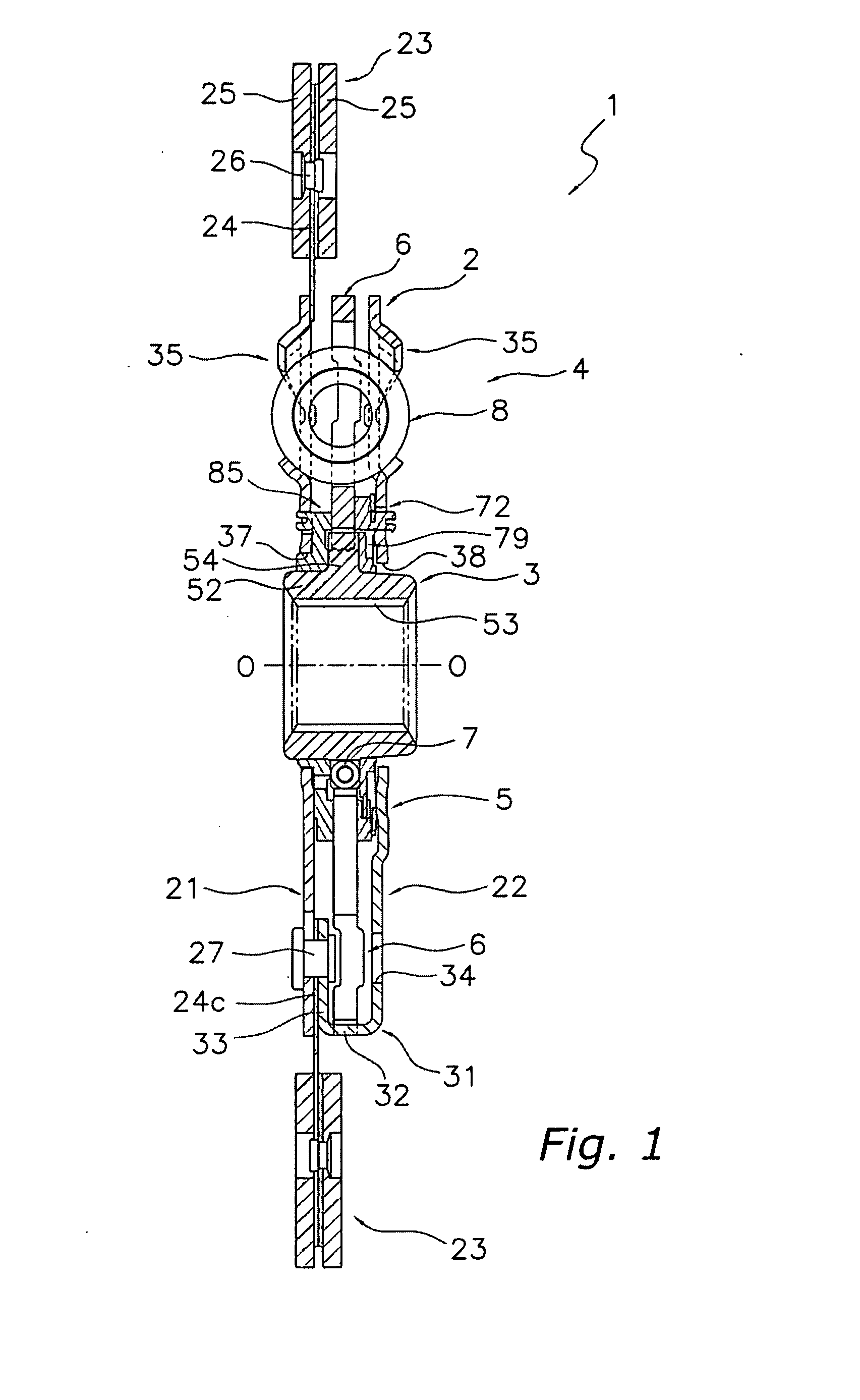
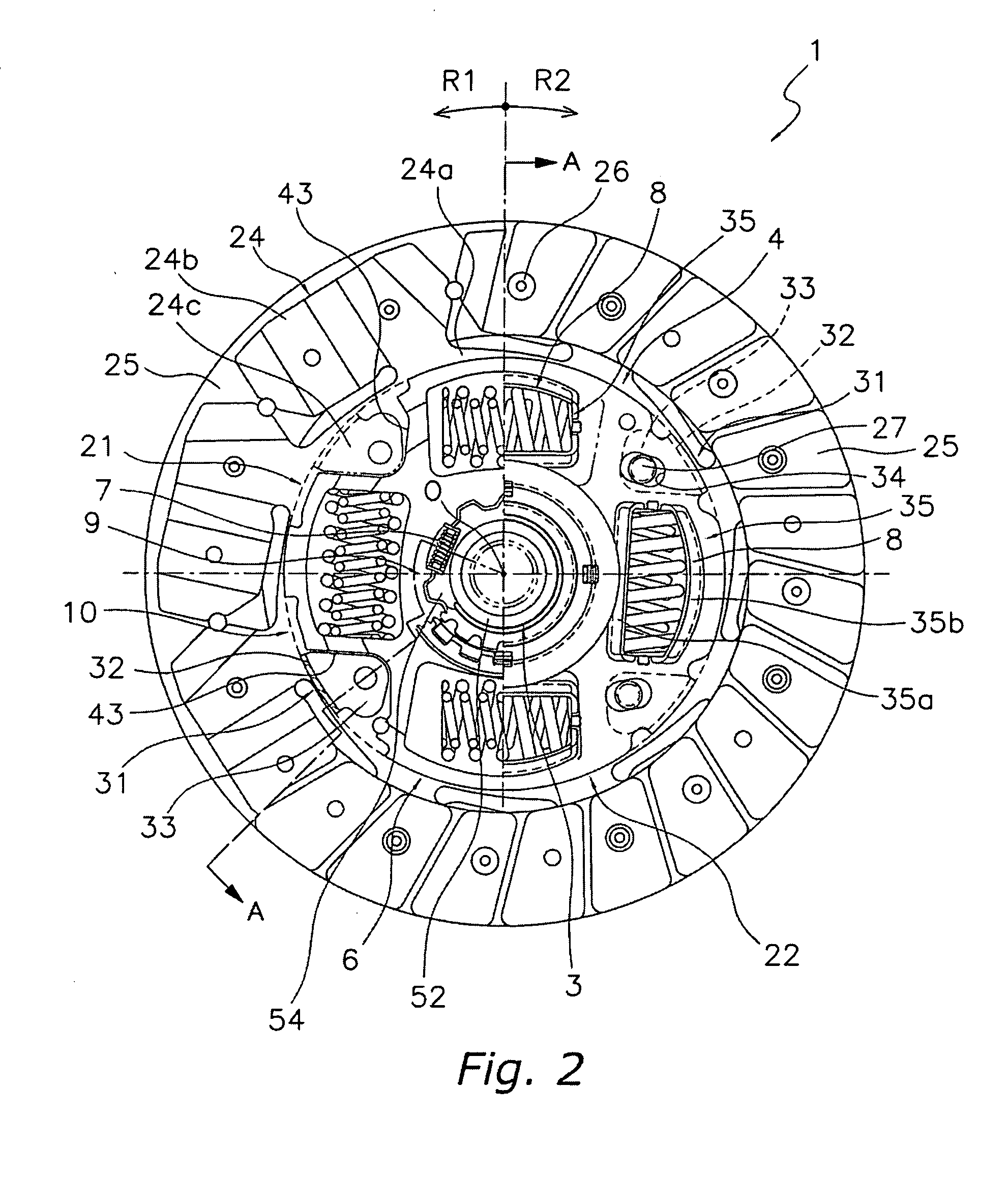
[0037]A clutch disk assembly 1 in which a damper mechanism 4 pertaining to the present invention has been installed will be described through reference to FIG. 1 or 2. FIG. 1 is a simplified vertical cross section of the clutch disk assembly 1, and FIG. 2 is a simplified elevational view of the clutch disk assembly 1. The O-O line in FIG. 1 is the rotational axis of Th clutch disk assembly 1. Also, an engine and a flywheel (not shown) are disposed on the left side in FIG. 1, and a transmission (not shown) is disposed on the right side in FIG. 1. Further, the R1 side in FIG. 2 is the rotational direction drive side (positive side) of the clutch disk assembly 1, while the R2 side is the opposite side (negati...


PUM


Abstract

A damper mechanism 4 has a clutch plate 21 and a retaining plate 22 disposed aligned in the axial direction, a hub flange 6 disposed relatively rotatably in the axial direction between the plates 21 and 22, and a second coil spring 8 for elastically linking the plates 21 and 22 to the hub flange 6 in the rotational direction. The plates 21 and 22 have a pair of first main body components 28, and a plurality of linking components 31 that are disposed in the rotational direction between first protrusions 49 and second protrusions57 and that link the pair of first main body components 28. The plurality of linking components 31 is disposed such that adjacent pitches are different.

Description

TECHNICAL FIELD[0001]The present invention relates to a damper mechanism, and more particularly relates to a damper mechanism for damping torsional vibration in a power transmission system.BACKGROUND OF THE INVENTION[0002]Damper mechanisms are used to damp torsional vibration in the power transmission systems of vehicles. A clutch device that transmits and shuts off torque to and from an engine will be described here as an example.[0003]A clutch device is made up of a clutch disk assembly that is disposed near a flywheel, and a clutch cover assembly for pressing the clutch disk assembly against the flywheel. The clutch disk assembly functions both as a clutch and as a damper.[0004]The clutch cover assembly has an annular clutch cover that is fixed to the flywheel, a pressure plate provided so as to be capable of moving in the axial direction and rotating integrally with respect to the clutch cover, and a diaphragm spring that biases the pressure plate toward the flywheel.[0005]The c...

Claims


Application Information

Patent Timeline
Patent Type & Authority Applications(United States)
IPC IPC(8): F16F15/134
CPCF16F15/123F16D13/68F16F15/134F16D13/64F16D3/12
Inventor HADA, TOMOKIUEHARA, HIROSHI
Owner EXEDY CORP
Why Eureka
Try Eureka