Artificial knee joint

Active Publication Date: 2007-12-18
KYOCERA CORP
View PDF13 Cites 64 Cited by
  • Summary
  • Abstract
  • Description
  • Claims
  • Application Information

AI Technical Summary

Benefits of technology

[0014]According to the present invention, it is possible to naturally perform a femur external rotational operation around an inner condyle operating in a living body, further, since the inner condyle of the femur component is not held completely, it is possible to make it small for a drag (a contact stress) acting on the sliding surface upon bending so as to evade the extraordinary abrasion and the damage of the sliding surface of the tibia component, and in addition, by preventing the femur component from lifting in the rotational movement, a large bending angle can be acquired without generating the excess tension in the ligaments around the artificial knee joint.
[0015]In addition, since the sliding surface at the outer and rear side of the tibia component is formed in a linear shape in the front-to-back direction, and the femoral component is allowed to be roll-backed to the rear side of the inner condyle, even in a rotational movement supported by an outer condyle, it is possible to make it

Problems solved by technology

However, the above described conventional artificial knee joint shown in FIG. 6 involves a problem such that a large drag (a contact stress) is generated on a sliding surface by a rotational movement generated between the tibia component and a femoral component upon bending so as to bring about an extraordinary abrasion and a damage of the sliding surface of the tibia component although an R curved surface provided at the front and rear sides of the sliding surface of the tibia component allows a stability in a front-to-back direction of the femoral component upon extending the knee joint.
In addition, in the conventional artificial knee joint shown in FIG. 7, since an inner condyle

Method used


Image

  • Artificial knee joint
  • Artificial knee joint
  • Artificial knee joint

Examples


Embodiment Construction

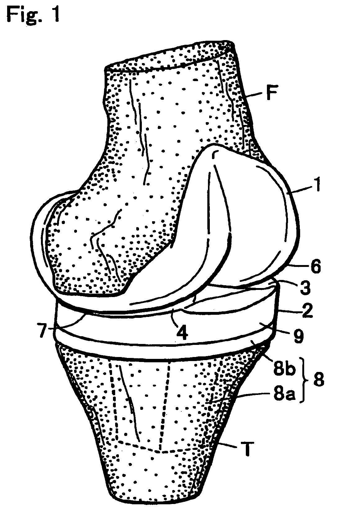
[0027]FIG. 1 shows the condition that the artificial knee joint according to the present invention is set at the knee joint region. The artificial knee joint is composed of a femoral component 1 to be secured to a distal portion of a femur F, and a tibia component 2 to be secured to a proximal portion of a tibia T. Among them, the tibia component 2 is composed of a tray member 8 in which a stem 8a to be embedded in the tibia and a tray 8b are integrally formed, and a sliding member 9 in which the femur component is sliding.

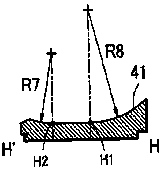
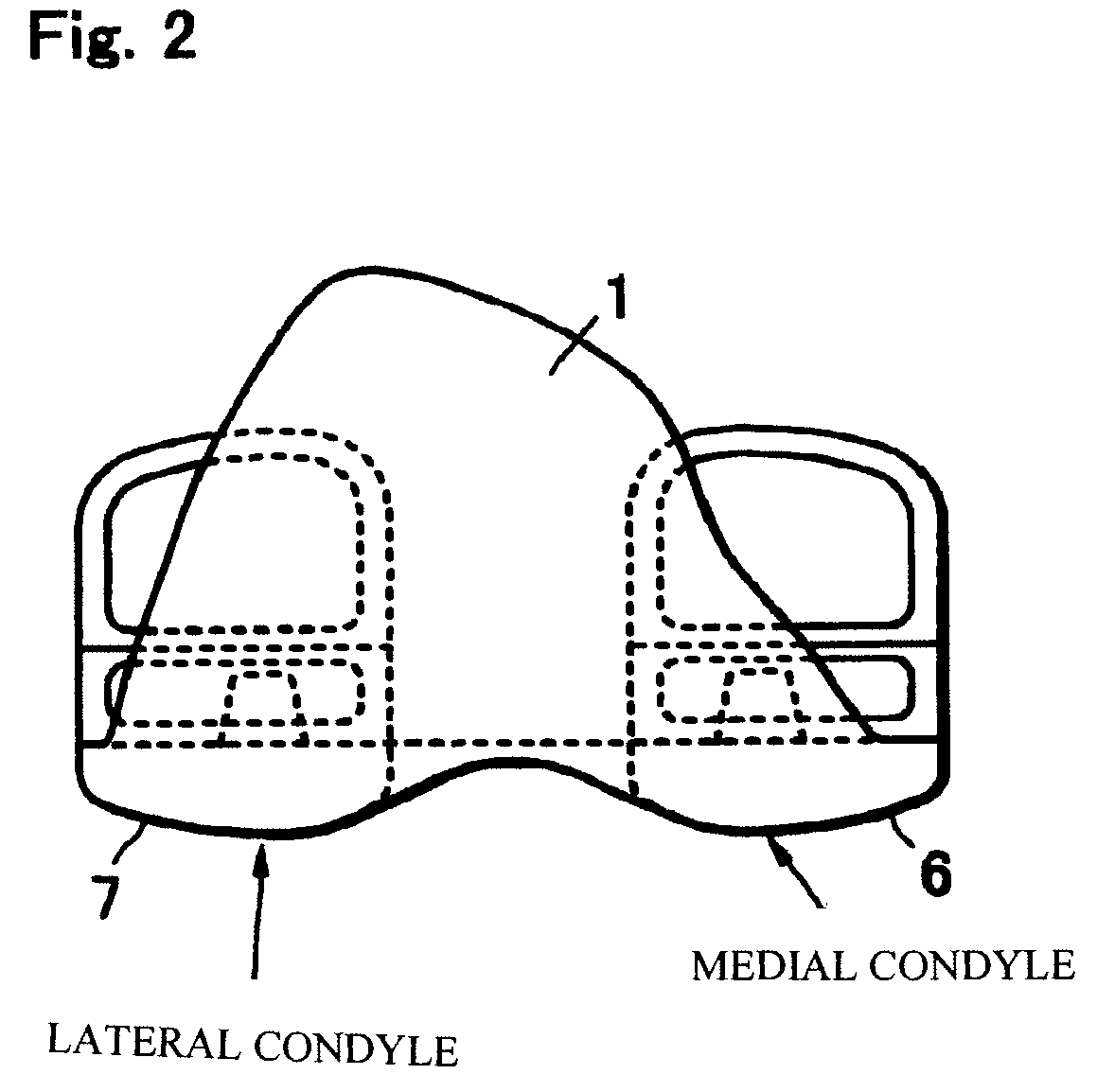
[0028]FIG. 2 is a front view of the femur component 1. In this femur component 1, an outer condyle sliding surface 7 and a inner condyle sliding surface G are formed at an outer condyle and an inner condyle, respectively, and they compose a joint surface by sliding an outer sliding surface 4 and an inner sliding surface 3 of the tibia component 2 to be described later.

[0029]In this case, a front-to-back (longitudinal) direction, an inner direction, and an outer di...


PUM


Abstract

An artificial knee joint, which makes a drag (a contact stress) acting on a sliding surface upon bending small so as to evade an extraordinary abrasion and damage of a sliding surface of a tibia component and which prevents an bending angle from being decreased by preventing lifting of a femoral component in a rotational movement. The artificial knee joint comprises a femoral component to be secured to a distal portion of a femur and a tibia component to be secured to a proximal portion of a tibia, comprising an inner sliding surface and an outer sliding surface receiving a load of the femoral component at the tibia component.
In the inner sliding surface, both of a front side and a rear side are formed in a sectional shape of circular arc in the front-to-back direction thereof, while in the outer sliding surface, a front side is formed in a sectional shape of a circular arc and a rear side is formed in a linear sectional shape in the front-to-back direction thereof.

Description

BACKGROUND OF THE INVENTION[0001]1. Field of the Invention[0002]The present invention relates to an artificial knee joint used to properly restore knee joints significantly deformed by chronic rheumatism, osteo-arthritis, pseudogout, and sudden osteonecrosis or the like.[0003]2. Description of the Related Art[0004]In a conventional artificial knee joint shown in FIG. 6, an inner sliding surface 30 and an outer sliding surface 40 of a tibia component 20 are shaped completely symmetrically, the inner sliding surface 30 and the outer sliding surface 40 make a circular arc having a curvature radius R3 at a front side at a longitudinal section and make a circular arc having a curvature radius R4 at a rear side at the longitudinal section, further, R3<R4 here.[0005]In addition, in other conventional artificial knee joint shown in FIG. 7, an inner sliding surface 31 and an outer sliding surface 41 are formed, which are asymmetrical to a tibia component 21 (see U.S. Pat. No. 6,013,103).[...

Claims


Application Information

Patent Timeline
IPC IPC(8): A61F2/38A61F2/00A61F2/30
CPCA61F2/38A61F2/3859A61F2/389A61F2002/30604A61F2310/00239A61F2310/00017A61F2310/00023A61F2310/00029A61F2310/00203A61F2002/30878
Inventor YASUDA, KAZUNORIYAMANASHI, WATARUSATAKE, SHIGERU
Owner KYOCERA CORP
Why Eureka
Try Eureka