Gate line drivers for active matrix displays

a technology of active matrix display and gate line driver, which is applied in the direction of digital storage, multiple input and output pulse circuit, instruments, etc., can solve the problems of affecting the stability of pull-down modules and the sr as a whole, affecting the normal operation of the pull-down module, etc., and achieve the effect of reducing the operational instability of the amorphous-silicon tft shift register

Active Publication Date: 2007-12-18
OPTRONIC SCI LLC
View PDF6 Cites 61 Cited by
  • Summary
  • Abstract
  • Description
  • Claims
  • Application Information

AI Technical Summary

Benefits of technology

[0017]The present invention provides a method to reduce the operational instability of an amorphous-silicon TFT shift register for driving a gate line in a TFT-LCD display. The shift register comprises a pull-up transistor Q2 and two pull-down modules. The shift register has an input terminal to receive a positive input pulse through the drain and the gate of a driving transistor Q1 and an output terminal to provide a positive output pulse, responsive to the input pulse. The output signal is provided at the source of the pull-up transistor. The gate of the pull-up transistor is connected to the source terminal of the driving transistor and the drain of the pull-up transistor is connected to a clock signal. The pull-up transistor produces a positive pulse when the clock signal is high and the gate of the pull-up transistor is also high. The voltage level at the gate of the pull-up transistor is pulled down to a negative voltage level Vss by two pull-down transistors (Q6, Q10) in the pull-down modules. Each of the pull-down modules also has a pull-down transistor (Q3, Q9) to keep the output terminal at the negative voltage Vss after the output pulse is produced. The two pull-down modules are operated in a cooperative manner so that each of the pull-down transistors (Q3, Q6, Q9, Q10) is conducting approximately 50% of the time. The gates of the pull-down transistors in the pull-down module are kept at a positive voltage level approximately 50% of the time and at a negative voltage level approximately 50% of the time. According to the present invention, the negative voltage level at the gates of the pull-down transistors is more negative than the voltage level Vss.

Problems solved by technology

The threshold drift may reduce the charge flow in the TFT, affecting its normal operations.
This increase may affect the instability of the pull-down modules and the SR as a whole.

Method used


Image

  • Gate line drivers for active matrix displays
  • Gate line drivers for active matrix displays
  • Gate line drivers for active matrix displays

Examples


Embodiment Construction

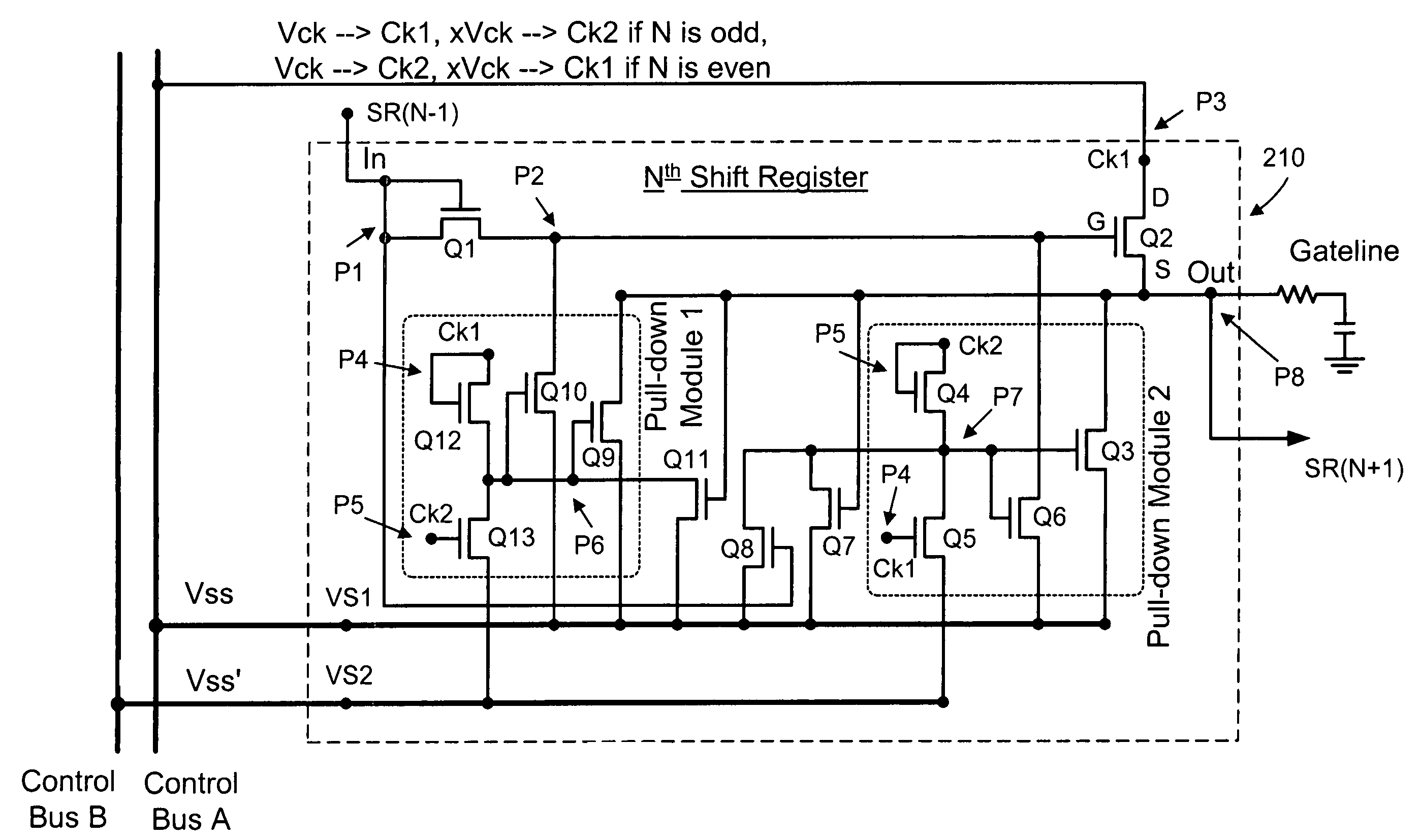
[0026]The present invention is illustrated in FIGS. 5 and 6. As shown in FIG. 5, an ASGD gate line driving circuit comprises a shift register module 200 connected to control bus A and control bus B. The shift register module 200 comprises a plurality of shift registers 210 connected in a cascaded fashion. Similar to the shift register 110 as shown in FIG. 2a , the shift register 210 has a pull-up TFT, a driving TFT and two pull-down modules.

[0027]Referring now to FIG. 6, the Nth shift register 210 has a pull-up TFT Q2 and a driving TFT Q1 for driving Q2. The gate and the drain of Q1 are connected to the input of the SR for receiving a positive pulse from the output of the preceding SR (N-1). The source of Q1 is connected to the gate G of Q2. The drain D of Q2 is connected to Ck1 for receiving a clock signal. The source S of Q2 is connected to the output of SR for providing a positive pulse in response to the input pulse and the clock signal. The source of Q2 is also connected to two...


PUM


Abstract

A shift register in an amorphous-silicon gate driver comprises a pull-up transistor and two pull-down modules. The pull-up transistor produces a positive pulse when the clock signal is high and the gate of the pull-up transistor is also high. The gate of the pull-up transistor is pulled down to a negative voltage level Vss by two pull-down transistors in the pull-down modules. Each pull-down module also has a further pull-down transistor to keep the output terminal at Vss after the output pulse is produced. The two pull-down modules are operated in a cooperative manner so that each pull-down transistor is conducting approximately 50% of the time. The gates of the pull-down transistors are kept at a positive voltage level approximately 50% of the time and at Vss′ approximately 50% of the time with Vss′ being more negative than Vss.

Description

[0001]The present invention is based on and claims priority to U.S. Provisional Application No. 60 / 727,886, filed Oct. 18, 2005.TECHNICAL FIELD OF THE INVENTION[0002]The present invention pertains to liquid crystal display (LCD) devices, and more specifically, to electrical circuits for driving the LCD devices.BACKGROUND OF THE INVENTION[0003]Thin-film transistor liquid-crystal display (TFT-LCD) is a flat-panel display device that displays images by an array of liquid-crystal pixels. As shown in FIG. 1, a typical TFT-LCD display panel 10 comprises a display module 20 having a plurality of pixels 21 arranged in a two-dimensional array. These pixels are controlled by a plurality of data lines D1, D2, . . . , Dn and a plurality of gate lines G1, G2, . . . , Gm. The data lines are connected to a data source driver 30 and the gate lines are connected to a gate line driver 40. A printed circuit board (PCB) 50 containing circuits necessary to convert image data into voltage signals is conn...

Claims


Application Information

Patent Timeline
Patent Type & Authority Patents(United States)
IPC IPC(8): H03K5/22
CPCG11C19/28
Inventor WEI, CHUN-CHINGWU, YANG-ENLIN, WEI-CHENG
Owner OPTRONIC SCI LLC
Why Eureka
Try Eureka