
System and method for verifying the dimensions of airfoils

a technology of airfoil and measurement method, which is applied in the field of measuring and verifying the dimensions of airfoils, can solve the problems of difficult to completely remove, easy to be distorted, and parts with high aspect ratio airfoils are particularly susceptibl

Active Publication Date: 2007-12-18
RTX CORP
View PDF2 Cites 6 Cited by
  • Summary
  • Abstract
  • Description
  • Claims
  • Application Information

AI Technical Summary

Benefits of technology

Enables accurate and independent verification of airfoil geometries, separating form and positional tolerances, thereby reducing distortion and improving the precision of airfoil dimensions within acceptable profile tolerances.

Problems solved by technology

This deviation is inherent in the process and, although it can be controlled, it cannot be completely removed.
Although this deviation is present, to some extent, on all castings, parts having high aspect ratio airfoils are particularly susceptible due to the relatively long, slender nature of the airfoils, which become easily distorted.
For instance, solidification induces stresses in the mold, which create distortion in the finished part.
This is an unavoidable result of the investment casting process.
It is not possible with the current datum system to distinguish a feature that has the correct form but is out of position from a feature that does not have the correct form.
Without independent verification of both the form and position it is not possible to determine accurately the amount of distortion of the part.
As positional deviation is often much larger than form deviation, combining the two results in an unacceptably large reported form tolerance during inspection.

Method used


Image

  • System and method for verifying the dimensions of airfoils
  • System and method for verifying the dimensions of airfoils
  • System and method for verifying the dimensions of airfoils

Examples


Embodiment Construction

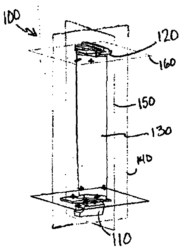
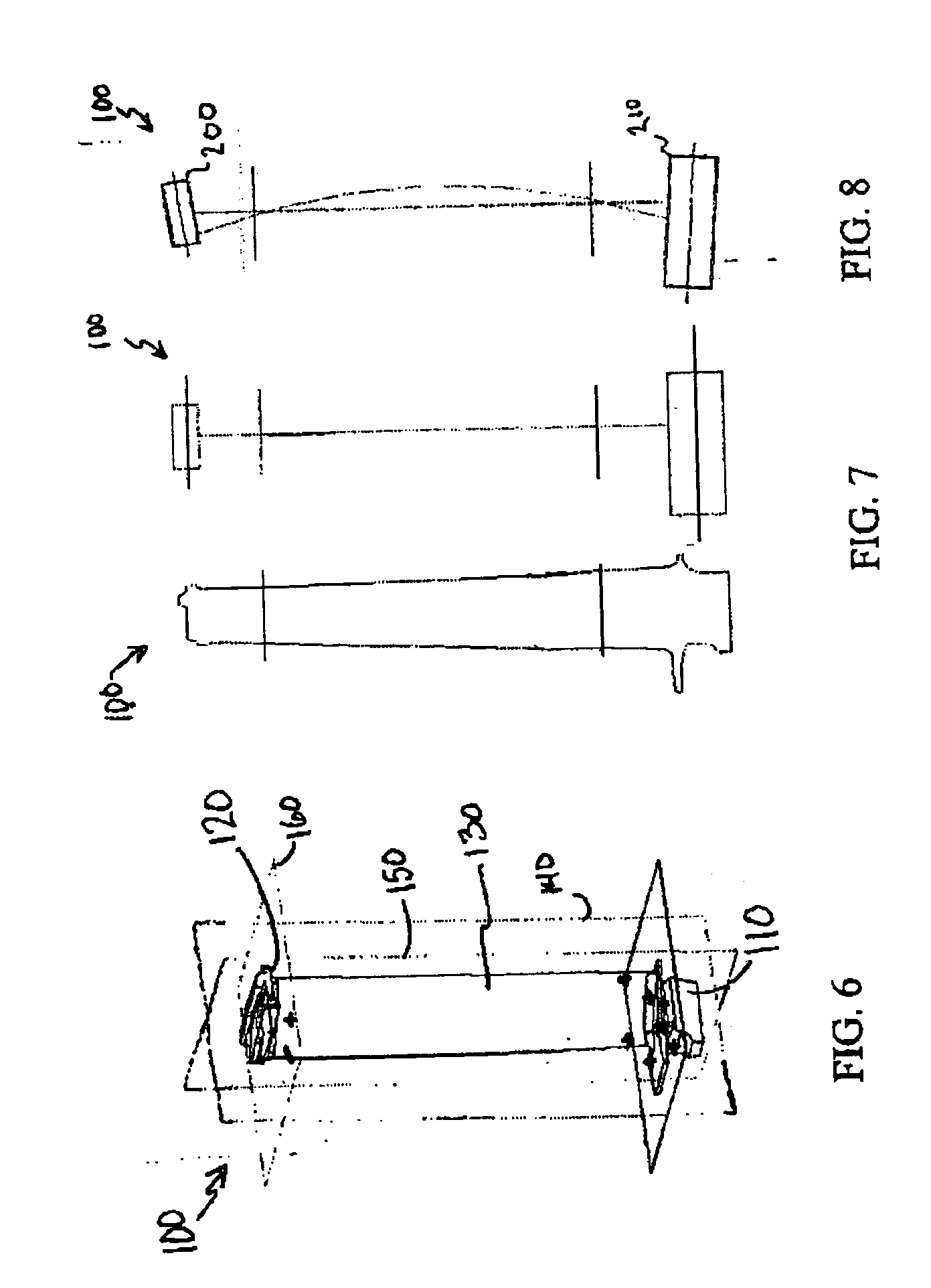
[0026]The system(s) and method(s) of the present invention verify the positional geometry of an airfoil independent of the form or the feature geometry of the airfoil, and vice versa. Rather than employing only one primary datum system, that is, a six point nest, as does the prior art, the present invention utilizes one or more additional datum systems, that is, one or more additional six point nests, to verify the positional geometry independently from the feature geometry. The system(s) and method(s) of the present invention may be implemented using hard nests utilizing primary and secondary datum systems and by performing hand layouts to verify the positional geometry independent of the feature geometry.

[0027]In the alternative, the system(s) and method(s) for verifying the positional geometry of an airfoil independent of the form or feature geometry of the airfoil, and vice versa, described herein may also be computer-implemented systems and methods, that is, a soft nest or a co...


PUM

PropertyMeasurementUnit
aspect ratioaaaaaaaaaa
shell strengthaaaaaaaaaa
dimensionsaaaaaaaaaa

Abstract

A computer-implemented method for verifying geometries of airfoils includes the steps of providing a part having an airfoil having an intended positional geometry and an intended feature geometry; measuring a first set of points of a primary datum system; determining an actual positional geometry of the airfoil based on the primary datum system measurements; calculating a first deviation between the intended positional geometry and the actual positional geometry of the airfoil; measuring a plurality of sets of points of at least one secondary datum system; determining an actual feature geometry of the airfoil based on the at least one secondary datum system measurement; calculating a second deviation between the intended feature geometry and the actual feature geometry of the airfoil; and performing a verification of the intended positional geometry and the intended feature geometry of the airfoil based upon the first deviation and the second deviation.

Description

U.S. GOVERNMENT RIGHTS[0001]The Government of the United States of America may have rights in the present invention pursuant to Contract No. F33657-99-D-2051-0010 awarded by the United States Air Force.FIELD OF USE[0002]The present disclosure relates to measuring airfoil geometries and, more particularly, to measuring and verifying airfoil geometries.BACKGROUND OF THE INVENTION[0003]Verifying the geometries of airfoil castings is required to detect deviations introduced during the casting process. A hard tool creates a very dimensionally accurate wax pattern but remainder of the investment casting process introduces geometric variability into the part. This deviation is inherent in the process and, although it can be controlled, it cannot be completely removed. Although this deviation is present, to some extent, on all castings, parts having high aspect ratio airfoils are particularly susceptible due to the relatively long, slender nature of the airfoils, which become easily distort...

Claims


Application Information

Patent Timeline
Patent Type & Authority Patents(United States)
IPC IPC(8): G01B5/00
CPCG01B21/20G05B19/401G05B19/4184Y10T29/49771G05B2219/35128Y02P90/02
Inventor MENTZ, KARL A.DUBE, BRYAN P.SALZILLO, JR., RICHARD M.
Owner RTX CORP
Learn More