Bend-straightening machine with vertically movable table

a vertically movable, straightening machine technology, applied in forging/hammering/pressing machines, manufacturing tools, shaping tools, etc., can solve the problems of asymmetric load on workpieces, limited machine tonnage and stroke capability, and less than perfect repeatability during measuremen

Inactive Publication Date: 2007-12-25
MAE EITEL
View PDF3 Cites 17 Cited by
  • Summary
  • Abstract
  • Description
  • Claims
  • Application Information

AI Technical Summary

Benefits of technology

[0010]Advantageously, the moving table will hold the straightening supports by a simple means and can be moved only in a defined, vertical direction relative to the base, upright column(s) and fixed bridge. This causes a load to be exerted by the straightening supports onto the workpiece only from below, independent of the diameter of the workpiece. Thus, a symmetrical load can be exerted on the workpiece by a simple means.

Problems solved by technology

This known bend-straightening machine operates satisfactorily, but has a disadvantage in that the tonnage and stroke capability of the machine are limited by ergonomic considerations when considering the floor-to-workpiece centerline distance.
Also, due to the plurality of springs supporting the bridge, deformation of any of springs will lead to an asymmetrical load on the workpiece.
In addition, the workpiece holding fixtures must be mounted on the fixed machine table and utilize a spring to achieve clamping position, resulting in less than perfect repeatability during measurement.
The overhead cam arrangement requires the drive mechanism to be mounted to the bridge, which is above the workpiece, requiring a significant support structure in large tonnage machines, thereby increasing its cost.
In addition, the workpiece holding fixtures must be mounted on the fixed machine table and utilize a spring to achieve clamping position, resulting in less than perfect repeatability during measurement.

Method used


Image

  • Bend-straightening machine with vertically movable table
  • Bend-straightening machine with vertically movable table
  • Bend-straightening machine with vertically movable table

Examples


Embodiment Construction

[0019]Preferred embodiments of the present disclosure will be described hereinbelow with reference to the accompanying drawings. In the following description, well-known functions or constructions are not described in detail to avoid obscuring the disclosure in unnecessary detail.

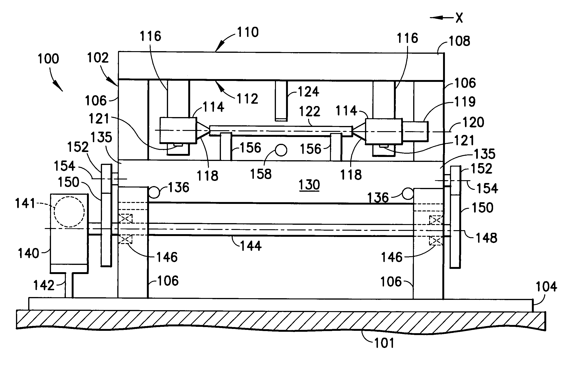
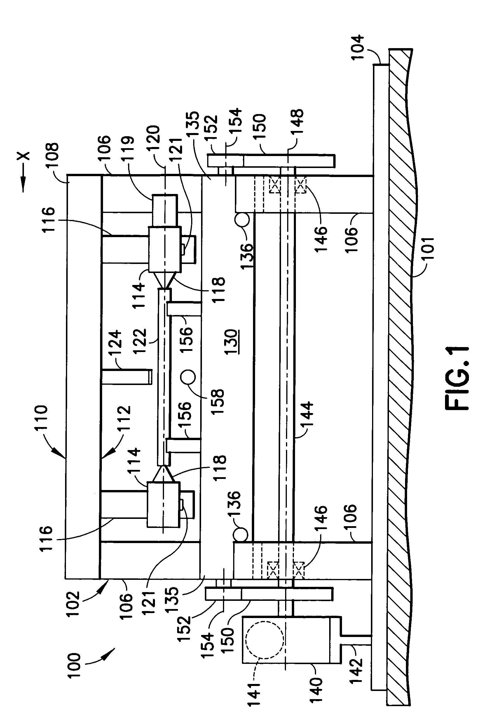
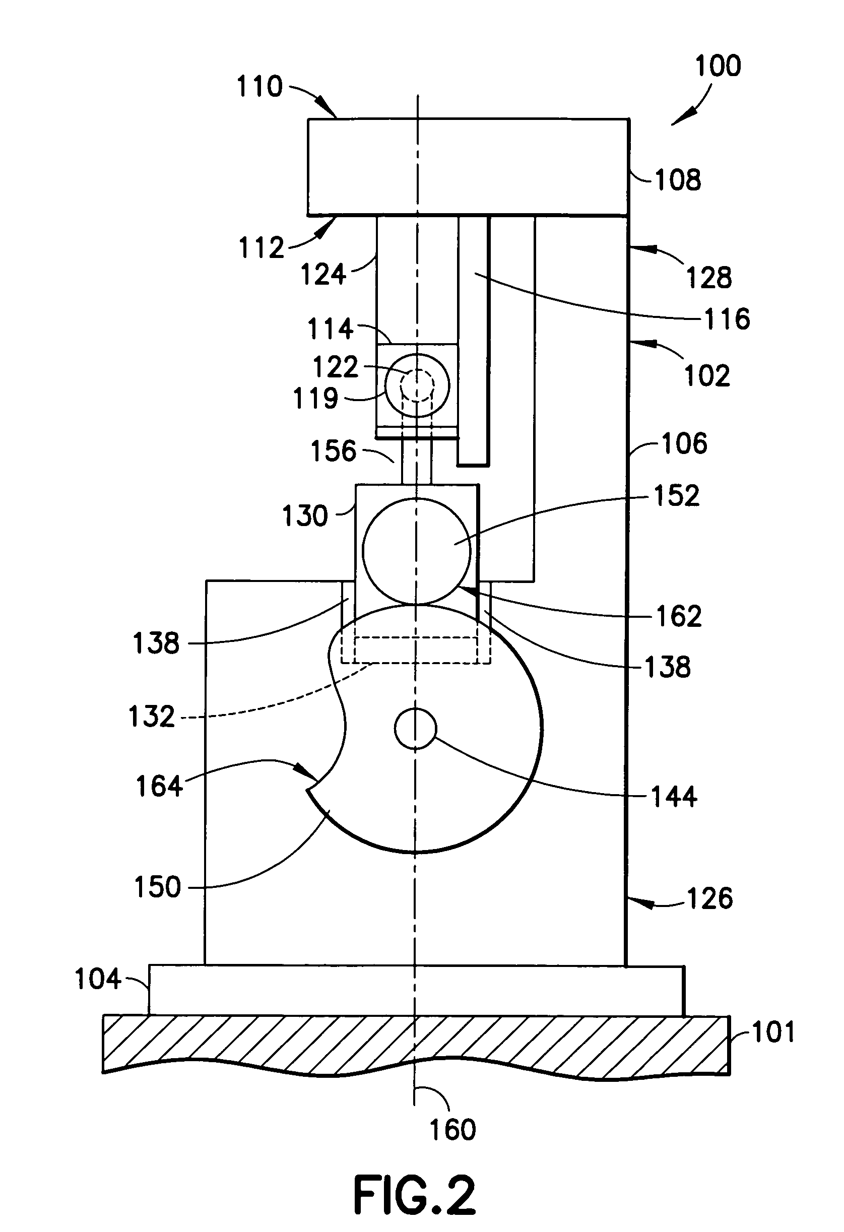
[0020]A bend-straightening machine in accordance with the present disclosure is illustrated in FIGS. 1 and 2 and is generally indicated by reference numeral 100. The machine 100 is generally constructed as a rigid, fixed frame 102. The frame 102 includes a generally rectangular base 104 for supporting the frame 102 on a floor 101, two upright columns 106 spaced apart on the base 104 and a fixed bridge 108 which is joined at each end to an upper portion of the upright columns 106. It is to be appreciated that the machine is constructed as an open frame which will allow for easy access to the workpiece and tooling as required by the straightening process.

[0021]The bridge 108 is generally rectangular and inclu...


PUM

PropertyMeasurementUnit
angleaaaaaaaaaa
angle of traverseaaaaaaaaaa
angleaaaaaaaaaa

Abstract

A bend-straightening machine with a vertically movable table for straightening long workpieces is provided. The bend-straightening machine of the present disclosure includes straightening supports for supporting a workpiece mounted on a movable table which moves in a vertical plane driven by a driving mechanism. The machine is constructed as a rigid frame including a base for supporting at least one upright column. A fixed bridge is joined to an upper portion of the upright column and supplies a stationary surface for mounting at least two workpiece holding fixtures, which grip the ends of the workpiece, allowing the workpiece to be rotated. Also, mounted to the bridge is at least one straightening punch which remains stationary during straightening. The moving table and straightening supports act vertically upward on the workpiece causing the workpiece to bend, i.e., straighten, when it contacts the straightening punch.

Description

BACKGROUND[0001]1. Field[0002]The present disclosure relates generally to bend-straightening machines for straightening workpieces, and more particularly, to a bend-straightening machine having a vertically movable table for driving the workpiece against a straightening punch.[0003]2. Description of the Related Art[0004]Bend-straightening machines are known in the art. An exemplary bend-straightening machine is described in U.S. Pat. No. 5,839,315, owned by the assignee of the present application. In U.S. Pat. No. 5,839,315, the actuating mechanism of the machine is based upon cam on roller technology, which utilizes a camshaft mounted in a stationary machine table below straightening bases. The actuating mechanism is designed as a bridge which holds a straightening ram in vertical alignment of a workpiece and the bridge can be moved in a vertical plane by means of a drive mechanism coupled to the camshaft. The bridge is spring-mounted on a base plate of the machine to urge the ram ...

Claims


Application Information

Patent Timeline
Patent Type & Authority Patents(United States)
IPC IPC(8): B21D7/06B21D37/12B21D9/05
CPCB21D3/10
Inventor RUPERT, REESE
Owner MAE EITEL
Why Eureka
Try Eureka