Electric stapler with pencil sharpener

a pencil sharpener and stapler technology, applied in the direction of stapling tools, nailing tools, printing, etc., can solve the problem of unnecessarily reducing the use area of the desk, and achieve the effect of convenient installation and us

Inactive Publication Date: 2007-12-25
PANASONIC CORP
View PDF14 Cites 16 Cited by
  • Summary
  • Abstract
  • Description
  • Claims
  • Application Information

AI Technical Summary

Benefits of technology

[0010]Therefore, it is an object of the present invention to provide an electric stapler with pencil sharpener that is formed by an electric stapler and an electric pencil sharpener integrated with each other so as to allow them to be conveniently installed and used.
[0013]In addition, a power transformer for generating DC power that serves as an electric driving source of the electric stapler is provided in the lower part in which the electric pencil sharpener is provided in the above structure. That is, the heavy power transformer is located in the lower part. Thus, a weight balance in the entire device is lowered and therefore stability is improved. Moreover, a volume of the electric stapler arranged in an upper part is reduced. Due to those, the entire size is reduced and the stability is more improved.
[0014]A shared AC-DC conversion circuit for supplying driving power to the electric pencil sharpener and the electric stapler may be provided. In this case, a power supply circuit is shared between the electric pencil sharpener and the electric stapler. Therefore, the number of components in the entire device is reduced, thus reducing the size and cost.
[0015]Moreover, a top face of a lower housing for accommodating the electric pencil sharpener may be formed as a shared surface that also serves as a bottom face of an upper housing for accommodating the electric stapler, and the shared surface may further serve as a paper table on which the bundle of paper inserted into the electric stapler is stapled. In this case, an outer package is simplified and the paper table that is an essential component of the electric stapler is formed in a simple manner.

Problems solved by technology

However, if it is demanded that both of the electric stapler and the electric pencil sharpener can be used, when those two devices are put on a desk, a useful area on the desk is unnecessarily reduced.

Method used


Image

  • Electric stapler with pencil sharpener
  • Electric stapler with pencil sharpener
  • Electric stapler with pencil sharpener

Examples


Embodiment Construction

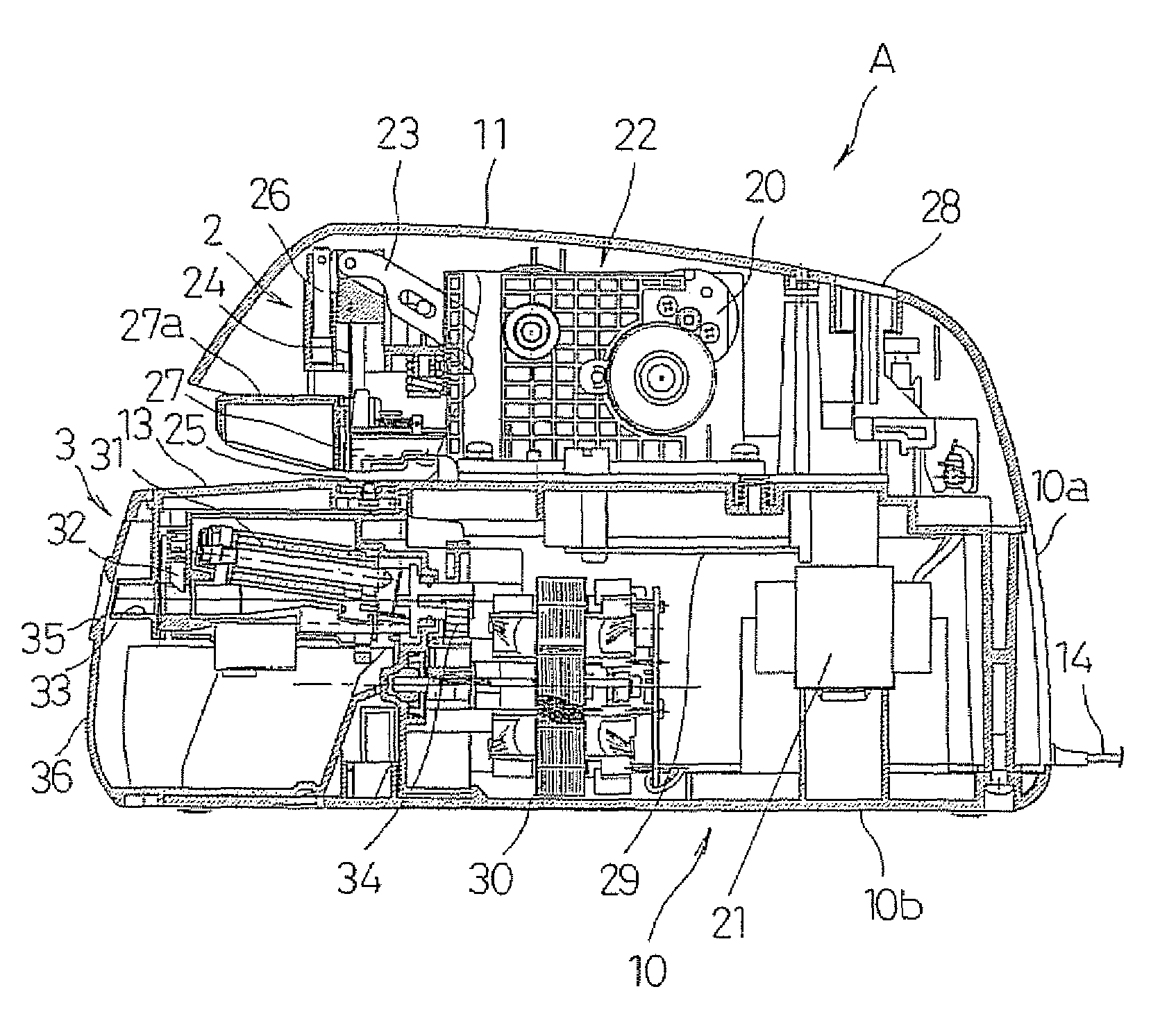
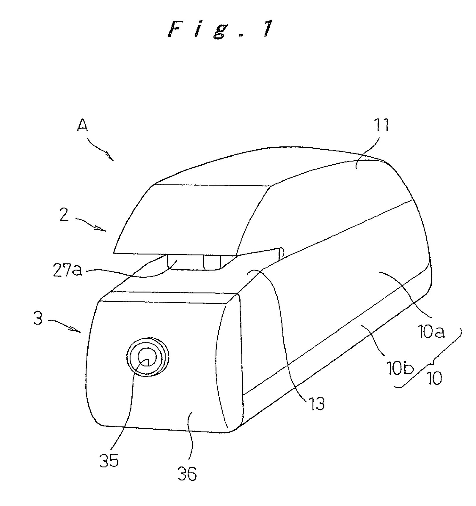
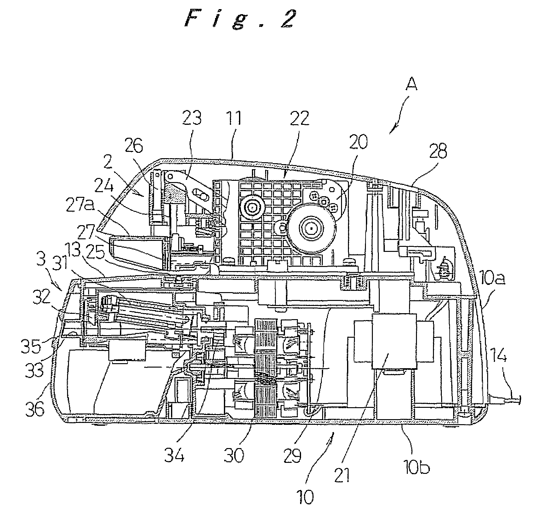
[0022]With reference to FIGS. 1 to 3, the present invention will now be described in accordance with the embodiments. Note that the embodiments do not intend to limit the scope of the present invention, but exemplify the invention.

[0023]FIG. 1 shows the appearance of an electric stapler with pencil sharpener A according to a first embodiment of the present invention. The electric stapler with pencil sharpener A is configured to include: a lower housing 10 consisting of a lower case 10b and a middle case 10a arranged on the lower case 10b; an upper housing 11 arranged on the lower housing 10; an electric stapler 2 accommodated in the upper housing 11; and an electric pencil sharpener 3 accommodated in the lower housing 10. A top face of the middle case 10a of the lower housing 10 and a bottom face of the upper housing 11 are formed as a surface 13 shared by the lower housing 10 and the upper housing 11. The shared surface 13 serves as a paper table on which a bundle of paper to be st...


PUM

PropertyMeasurementUnit
DC poweraaaaaaaaaa
driving poweraaaaaaaaaa
volumesaaaaaaaaaa

Abstract

An electric pencil sharpener is accommodated in a front part of a lower housing. An electric stapler is accommodated in an upper housing including a shared surface that is used as a top face of the lower housing, as its bottom face. A power transformer for supplying DC power to the electric stapler is arranged in a rear part of the lower housing. The shared surface also serves as a paper table used for guiding a bundle of paper into the electric stapler. A caulking plate for bending both legs of a staple that is made to penetrate through the bundle of paper by a hammer is provided on the shared surface. Since the electric stapler is arranged in an upper part and the electric pencil sharpener is arranged in a lower part, it is possible to provide an electric stapler with pencil sharpener in which cutting waste generated by sharpening a pencil does not affect the stapling operation and good stability is achieved because of a lowered weight balance and which requires only a small installation area on a desk.

Description

[0001]The present disclosure relates to subject matter contained in priority Japanese Patent Application No. 2005-155200, filed on May 27, 2005, the contents of which is herein expressly incorporated by reference in its entirety.BACKGROUND OF THE INVENTION[0002]1. Field of the Invention[0003]The present invention relates to an electric stapler with pencil sharpener in which an electric stapler and an electric pencil sharpener are integrated with each other as one unit.[0004]2. Description of the Related Art[0005]An electric stapler can automatically staple a plurality of sheets of paper together only by inserting the plurality of sheets of paper into a predetermined stapling position, thereby improving efficiency of office work that handles volumes of documentation or the like. As such an electric stapler, a conventional technique shown in FIG. 4 is known (see Japanese Patent Publication No. 2000-153469, for example).[0006]This type of electric stapler can be operated as follows: AC...

Claims


Application Information

Patent Timeline
Patent Type & Authority Patents(United States)
IPC IPC(8): B25C5/15
CPCB25C5/0228B43L23/02B43L23/008
Inventor AOKI, TOMOAKI
Owner PANASONIC CORP
Why Eureka
Try Eureka