Compact compression connector with flexible clamp for corrugated coaxial cable

Inactive Publication Date: 2007-12-25
JOHN MEZZALINGUA ASSOC INC
View PDF48 Cites 64 Cited by
  • Summary
  • Abstract
  • Description
  • Claims
  • Application Information

AI Technical Summary

Benefits of technology

[0009]These and other needs are met by a compact compression connector for a segment of corrugated coaxial cable, wherein the segment of corrugated coaxial cable includes a center conductor, a plurality of conductive peaks, a plurality of conductive valleys, and a protective outerjacket. The end of a segment of coaxial cable is prepared by stripping away certain layers thereof at specified dista

Problems solved by technology

In general, it has proven difficult to adequately make such connections without requiring labor intensive effort by highly skilled technicians.
Moreover, even if careful attention is paid during installation, there still can be set up errors, which, in turn, can moderately to severely affect signal quality.
These problems are likewise encountered with respect to corrugated coaxial cable (e.g., spiral, helical and annular corrugated coaxial able), which is a type of cable that includes a plurality of ridges (i.e., peaks) on its outer conductor and a recessed valley between adjoining peaks.
The design of corrugated coaxial cable renders it well suited for usage conditions in which flexibility, strength and/or moisture resistance is desired, but also makes it challenging to properly engage the cable to a connector, especially in a field installation setting.
Unfortunately, this ideal positioning rarely occurs in practice due to various factors, most notably the design of the portion of the connector that contacts the outer conductor of the corrugated coaxial cable.
However, due to the design (e.g., a C-shaped design as described in U.S. Pat. No. 5,284,449 to Vaccaro, the entirety of which is incorporated by reference herein) and/or composition (e.g., metallic material) of these clamping mechanisms, such ideal positioning rarely occurs in

Method used


Image

  • Compact compression connector with flexible clamp for corrugated coaxial cable
  • Compact compression connector with flexible clamp for corrugated coaxial cable
  • Compact compression connector with flexible clamp for corrugated coaxial cable

Examples


Embodiment Construction

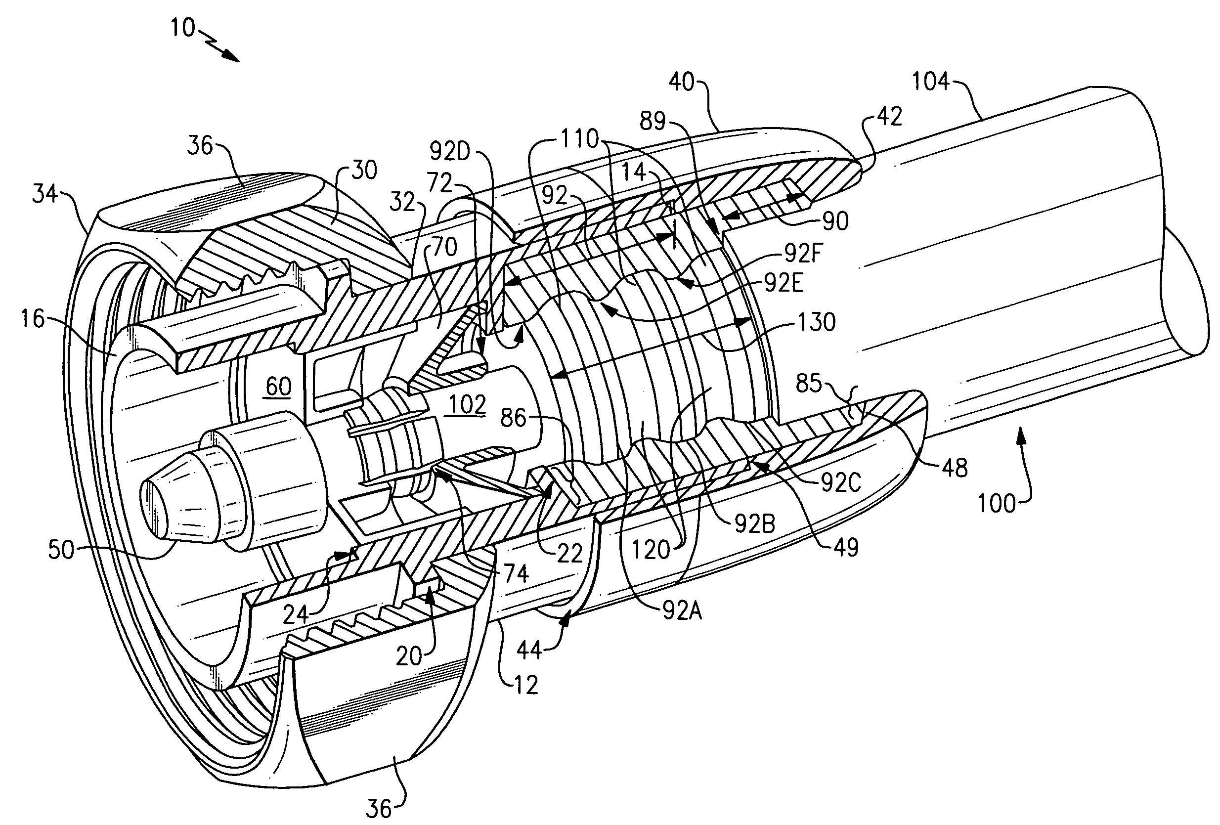
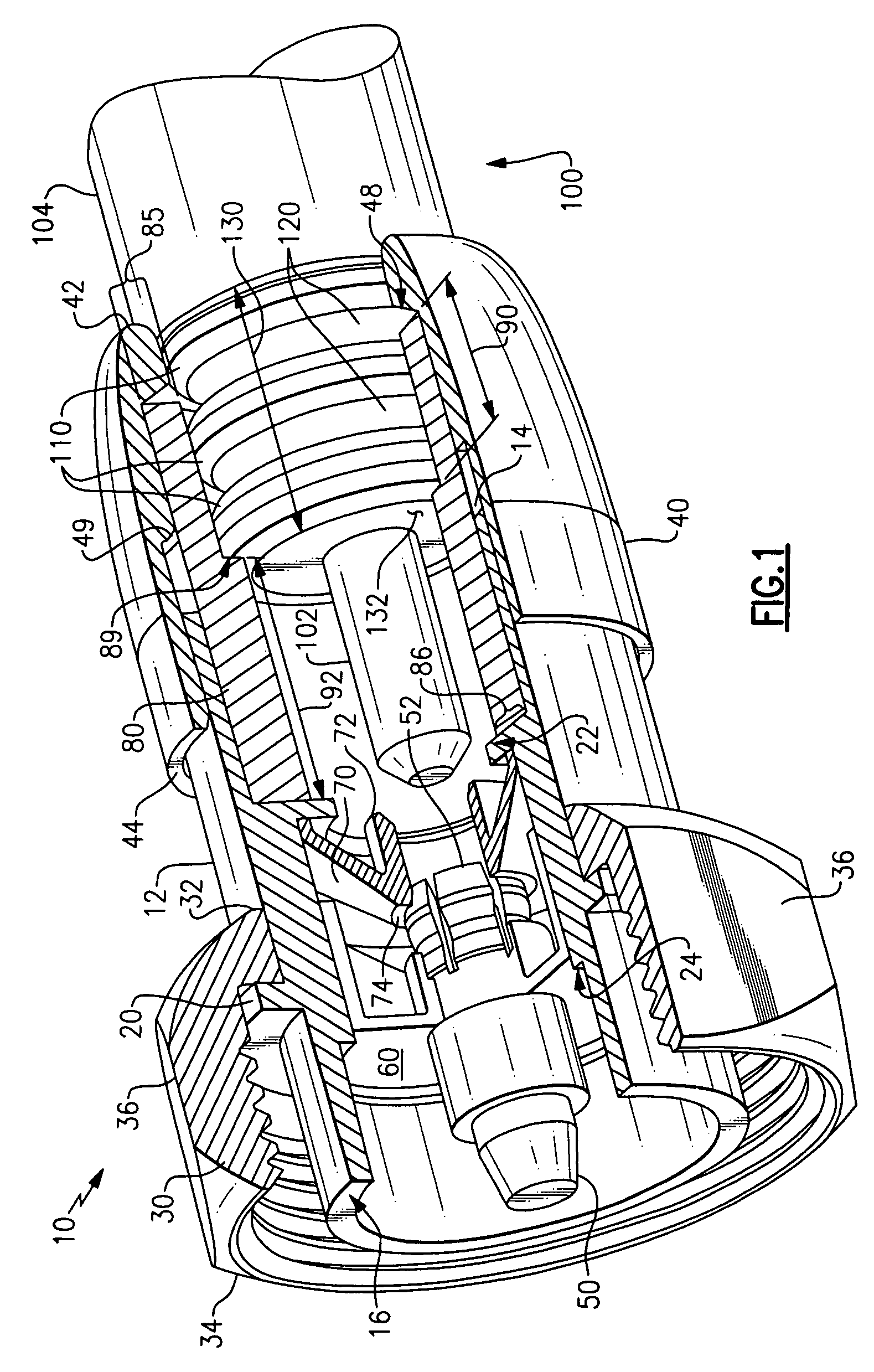
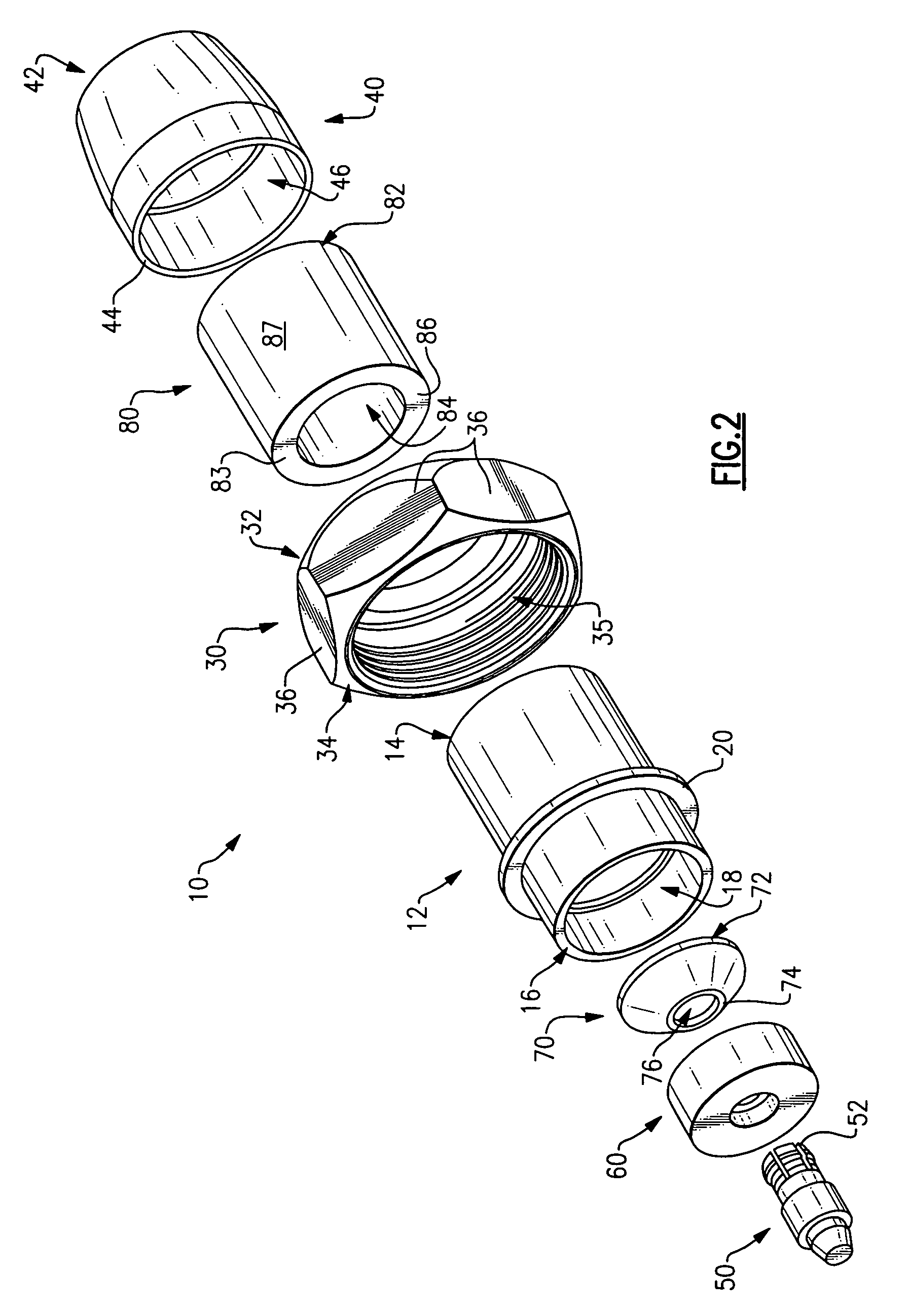
[0025]Referring initially to FIGS. 1 and 2, an exemplary compression connector 10 is shown, as is a portion of a segment of corrugated coaxial cable 100. In the illustrated embodiment, the corrugated cable segment 100 is annular corrugated coaxial cable; however, it should be noted that each of the embodiments described herein is equally applicable to all types of corrugated coaxial cable, including, but not limited to, annular corrugated coaxial cable, spiral corrugated coaxial cable, and helical corrugated coaxial cable. However, regardless of the specific type of corrugated coaxial cable, and as shown in FIG. 1, the cable segment 100 generally includes a distally protruding center conductor 102, an outer protective jacket 104, a plurality of conductive corrugation peaks 110, and a plurality of conductive valleys 120. The peaks 110 and valleys 120 collectively form what is hereinafter referred to as the “exposed corrugated region” of the corrugated coaxial cable segment 100, where...


PUM


Abstract

A compression connector for the end of a segment of corrugated coaxial cable is provided wherein the compression connector includes a clamp that is both flexible and conductive so as to enable a highly precise and secure, yet low stress engagement of the connector to the segment of corrugated coaxial cable.

Description

FIELD OF THE INVENTION[0001]This invention relates in general to terminals for coaxial cables, and, more particularly, to compact compression connectors that include a flexible, conductive clamp that can deform to facilitate a highly precise and secure, yet low stress engagement of the connector to a segment of corrugated coaxial cable.BACKGROUND OF THE INVENTION[0002]Coaxial cable is being deployed on a widespread basis in order to carry signals for communications networks, e.g., CATV and computer networks. Various types of coaxial cable must at some point be connected to network equipment ports. In general, it has proven difficult to adequately make such connections without requiring labor intensive effort by highly skilled technicians. Moreover, even if careful attention is paid during installation, there still can be set up errors, which, in turn, can moderately to severely affect signal quality.[0003]These problems are likewise encountered with respect to corrugated coaxial cab...

Claims


Application Information

Patent Timeline
IPC IPC(8): H01R9/05
CPCH01R9/0521H01R9/0527H01R13/6599H01R24/564H01R13/035H01R2103/00H01R13/2414
Inventor JACKSON, DAVIDMONTENA, NOAH
Owner JOHN MEZZALINGUA ASSOC INC
Why Eureka
Try Eureka