Electrical connectors

a technology of electrical connectors and connectors, applied in the direction of coupling bases/cases, coupling contact members, electrical apparatus, etc., can solve the problems of affecting the service life of the connector, the risk of damage to the connector,

Active Publication Date: 2007-12-25
SMITHS GRP PLC
View PDF10 Cites 106 Cited by
  • Summary
  • Abstract
  • Description
  • Claims
  • Application Information

AI Technical Summary

Problems solved by technology

Existing connectors are not generally suitable because they present too high an inductance.
Also, the relatively low number of contact points in conventional connectors means that each contact point has to pass a relatively high current with the consequent risk of damage to the connector.

Method used


Image

  • Electrical connectors
  • Electrical connectors
  • Electrical connectors

Examples


Embodiment Construction

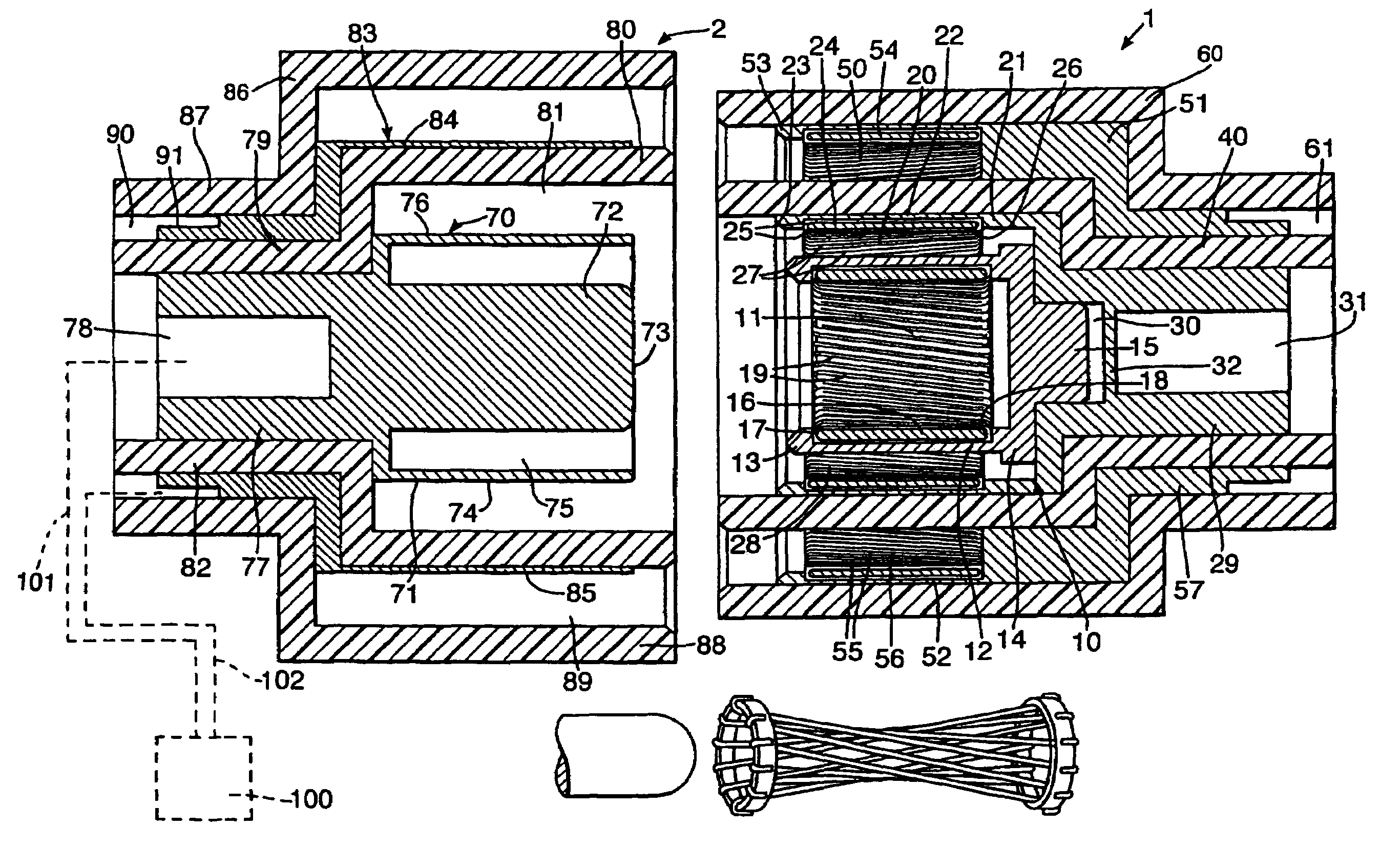
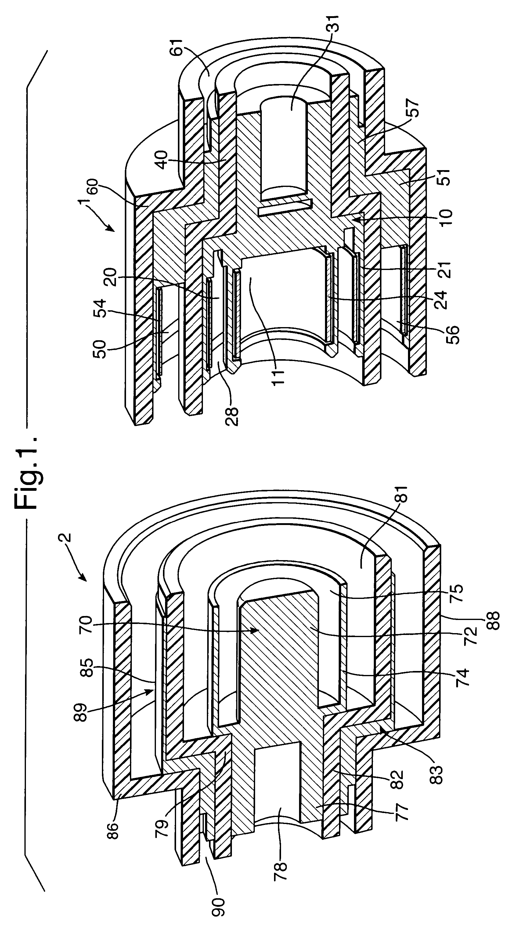
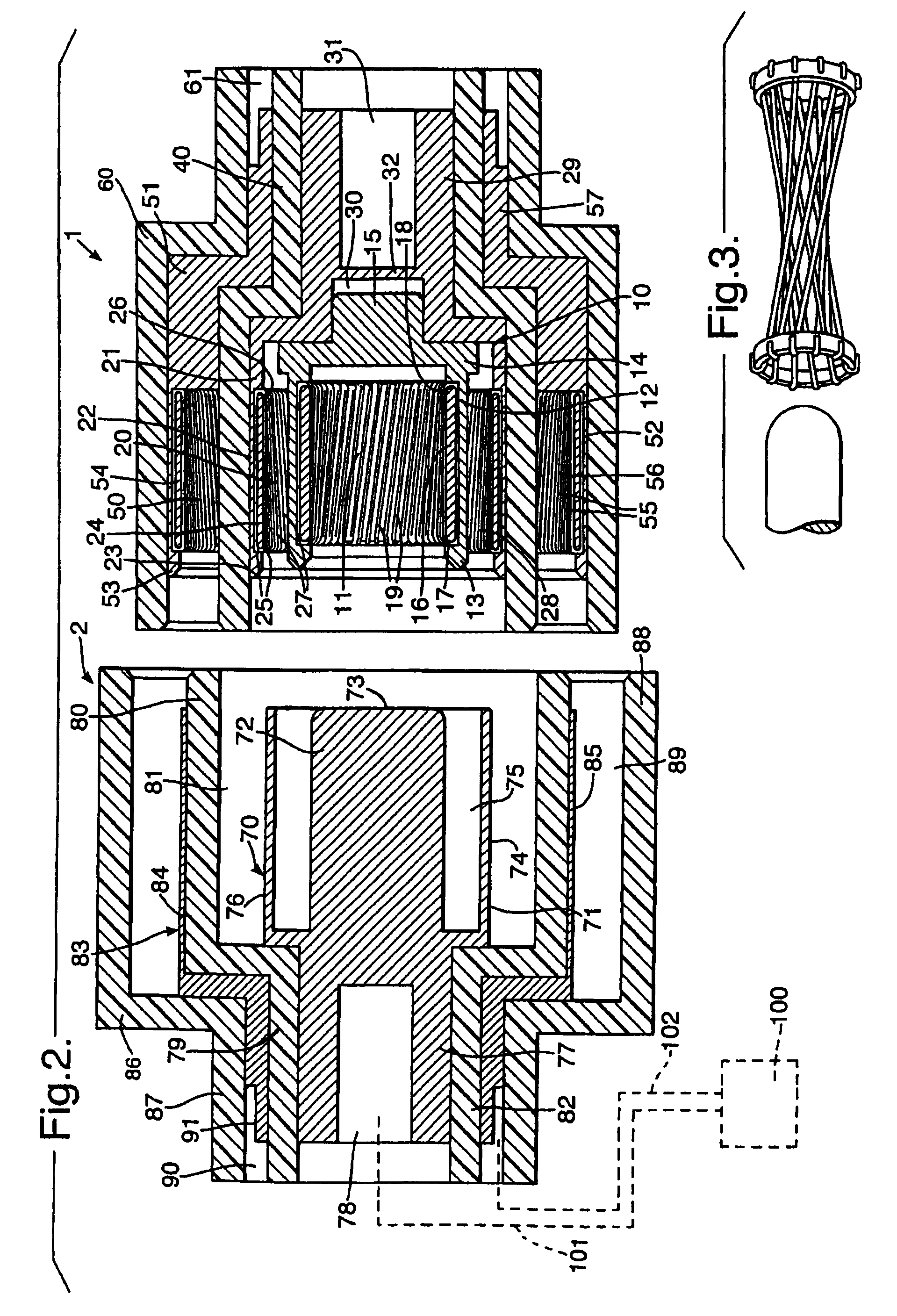
[0016]The connector comprises a female, socket assembly 1 and a male, pin or plug assembly 2 adapted to mate with one another and establish electrical interconnection along two paths: an outgoing path and a return path. The construction of the connector is such that it can reliably pass surge currents of up to about 300 KA for 5 ms.

[0017]The socket assembly 1 has an inner electrically-conductive sub-assembly 10 of a metal such as copper alloy. The sub-assembly 10 provides an inner socket 11 and an intermediate socket 20. The inner socket 11 has a machined collar 12 of cylindrical, tubular shape and circular section with an open forward end 13 and a closed rear end 14 formed with an axially protruding boss 15. Inside, the collar 12 retains a metal support sleeve 16, which is trapped between forward and rear shoulders 17 and 18 on the inner surface of the collar. The sleeve 16 supports multiple, resilient electrical contact wires 19 extending along the inner surface of the sleeve and ...


PUM


Abstract

An electrical connector for high current applications has a mating plug and socket assembly. The socket assembly has two sockets arranged coaxially of one another and electrically interconnected. The central socket receives and contacts a pin on the plug assembly; the other socket contacts the external surface of a tubular sleeve surrounding and integrally electrically connected with the pin. The socket assembly also has a third socket electrically insulated from and arranged coaxially outwardly of the other two sockets. The third socket makes electrical contact with the outer surface of a tubular contact extending coaxially of the pin and electrically insulated from it. The sockets each have a hyperboloid configuration of multiple resilient wires to make contact with the pin, sleeve and outer contact.

Description

BACKGROUND OF THE INVENTION[0001]This invention relates to electrical connectors and to socket and plug assemblies of such connectors.[0002]The invention is more particularly concerned with electrical connectors capable of handling short duration surges of very high current.[0003]There are some applications where it is necessary to deliver very high currents for short periods. Existing connectors are not generally suitable because they present too high an inductance. Also, the relatively low number of contact points in conventional connectors means that each contact point has to pass a relatively high current with the consequent risk of damage to the connector.BRIEF SUMMARY OF THE INVENTION[0004]It is an object of the present invention to provide an alternative electrical connector and plug and socket assemblies.[0005]According to one aspect of the present invention there is provided a socket assembly including a first socket arrangement having an inner contact surface provided by f...

Claims


Application Information

Patent Timeline
Patent Type & Authority Patents(United States)
IPC IPC(8): H01R13/187H01R13/33H01R13/53
CPCH01R13/187H01R13/53H01R13/33
Inventor DENT, PETER
Owner SMITHS GRP PLC
Why Eureka
Try Eureka