
Combined-type curved surface line light condensation device

A line concentrating and composite technology, applied in the field of solar energy utilization, can solve the problems of thick overall structure, long concentrating optical path, and large space occupation, so as to reduce the overall thickness, increase the optical path, and improve the converging efficiency Effect

Inactive Publication Date: 2015-11-18
CHENGDU ZSUN SCI & TECH DEVING
View PDF6 Cites 0 Cited by
  • Summary
  • Abstract
  • Description
  • Claims
  • Application Information

AI Technical Summary

Problems solved by technology

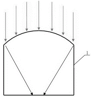
[0002] Concentrator is an important part of solar photovoltaic concentrating components, such as figure 1 As shown, the current line concentrator adopts a single convex concentrating form, which can converge the incident light through the convex surface. The main disadvantages of this structure are high cost, large space occupation, long focal length, and large waste of materials. , the problem of heavy weight
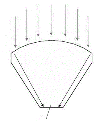
[0003] In order to overcome the above technical problems, there is currently a lightweight concentrator, such as figure 2 shown, it will figure 1 The ineffective areas on the left and right sides of the concentrating unit in use are removed, which has achieved the purpose of saving materials and reducing weight, and then its improved structure still adopts a single convex concentrating form, resulting in low converging efficiency, and its required The concentrating optical path is still long, resulting in a thicker overall structure and overweight, which requires higher strength for the mounting bracket and is not easy to install

Method used


Image

  • Combined-type curved surface line light condensation device
  • Combined-type curved surface line light condensation device
  • Combined-type curved surface line light condensation device

Examples


Embodiment Construction

[0013] Below in conjunction with accompanying drawing, the present invention is described in detail.

[0014] In order to make the object, technical solution and advantages of the present invention clearer, the present invention will be further described in detail below in conjunction with the accompanying drawings and embodiments. It should be understood that the specific embodiments described here are only used to explain the present invention, not to limit the present invention.

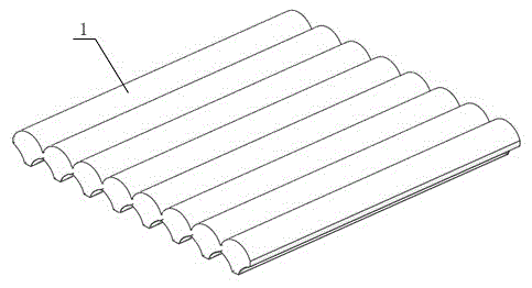
[0015] Such as image 3 and 4 As shown, a compound curved surface line concentrator is composed of several concentrating units 1 arranged in sequence, the lower parts of the two sides of the concentrating unit 1 are gradually inclined toward the center along the axial direction, and the concentrating unit 1 The upper end surface is a circular arc-shaped light-gathering refraction surface, and its lower end surface is a flat surface. The inclined surfaces on both sides of the light-gathering unit...


PUM


Abstract

The invention discloses a combined-type curved surface line light condensation device, which is composed of a plurality of sequentially arranged light condensation units, wherein the lower parts at two sides of each light condensation unit gradually incline towards the center thereof along the axial direction, the upper end face of the light condensation unit is a circular-arc-shaped light condensation refracting surface, the lower end face of the light condensation unit is a flat surface, the inclined surfaces at two sides of each light condensation unit are of a double curved surface structure which protrudes towards the center and is symmetrically arranged, the outer side of the double curved surface structure is plated with a reflecting material so as to form a reflecting surface, and light refracted by the light condensation refracting surface or light which is firstly refracted by the light condensation refracting surface and then reflected by reflecting surface of the double curved surface structure totally shoots to an area corresponding to the lower end face of the light condensation unit. According to the invention, the two side surfaces of each light condensation unit are designed to be the biconvex structure with a reflecting function, so that all incident light passing through the light condensation refracting surface can be ensured to shot into the area corresponding to the lower end face of the light condensation unit under the condition of reducing the overall thickness of the light condensation unit.

Description

technical field [0001] The invention belongs to the technical field of solar energy utilization, in particular to a composite curved surface line concentrator. Background technique [0002] Concentrator is an important part of solar photovoltaic concentrating components, such as figure 1 As shown, the current line concentrator adopts a single convex concentrating form, which can converge the incident light through the convex surface. The main disadvantages of this structure are high cost, large space occupation, long focal length, and large waste of materials. , the problem of heavy weight. [0003] In order to overcome the above technical problems, there is currently a lightweight concentrator, such as figure 2 shown, it will figure 1 The ineffective areas on the left and right sides of the concentrating unit in use are removed, which has achieved the purpose of saving materials and reducing weight, and then its improved structure still adopts a single convex concentrat...

Claims


Application Information

Patent Timeline
IPC IPC(8): G02B19/00
Inventor 黄忠
Owner CHENGDU ZSUN SCI & TECH DEVING
Learn More