Lancet having adjustable penetration depth

a technology of lancet and depth, which is applied in the field of lancet devices whose penetration depth, can solve the problems of crowded field relating to disposable and reusable lancet devices, and achieve the effects of reducing manufacturing costs, and reducing the risk of injury

Inactive Publication Date: 2007-12-25
STAT MEDICAL DEVICES
View PDF102 Cites 145 Cited by
  • Summary
  • Abstract
  • Description
  • Claims
  • Application Information

AI Technical Summary

Benefits of technology

[0017]It is another object of the present invention to provide a lancet device having a penetration depth adjustment mechanism which is contained entirely within a housing to reduce the possibility of accidental misadjustment of the penetration.
[0018]It is another object of the present invention to provide a lancet device having a penetration depth adjustment mechanism with a simplified cap construction.
[0019]It is an object of the present invention to provide a lancet device which is substantially cost effective to manufacture due to a small number of individual pieces to be put together, yet will still be substantially safe during use.
[0020]Still another object of the present invention is to provide a lancet device which provides for facilitated and effective cap positioning by impaired individuals.
[0021]Yet another object of the present invention is to provide a lancet device which is comfortably positionable within a user's hand and will not roll around within a user's hand or on a flat surface.
[0023]Further, the device of the present invention is designed to be utilized by individuals to do their own routine blood test such as individuals who do home monitoring of their blood such as diabetes patients. As a result, the present invention requires precise adaptation to make it effective yet safe for the user. As a result, the device of the present invention is comprised of a small number of individual pieces, thereby making the lancet device easier and substantially more cost effective to manufacture and provide for use by patients, without compromising any of the safety needs and in fact increasing the safety of use.

Problems solved by technology

The field relating to disposable and reusable lancet devices is substantially crowded.

Method used


Image

  • Lancet having adjustable penetration depth
  • Lancet having adjustable penetration depth
  • Lancet having adjustable penetration depth

Examples


Embodiment Construction

[0088]The particulars shown herein are by way of example and for purposes of illustrative discussion of the various embodiments of the present invention only and are presented in the cause of providing what is believed to be the most useful and readily understood description of the principles and conceptual aspects of the invention. In this regard, no attempt is made to show details of the invention in more detail than is necessary for a fundamental understanding of the invention, the description taken with the drawings making apparent to those skilled in the art how the several forms of the invention may be embodied in practice.

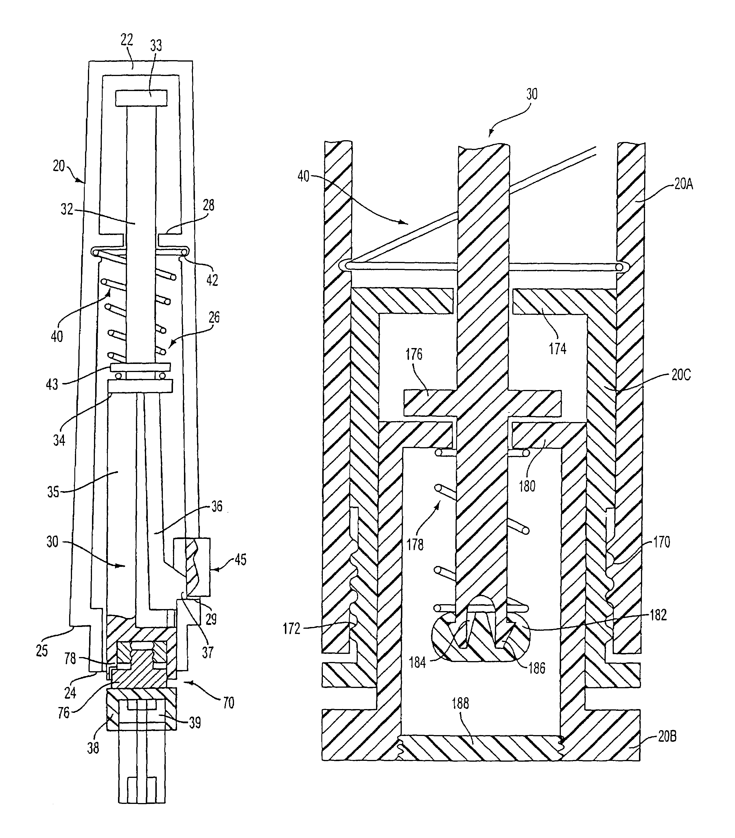
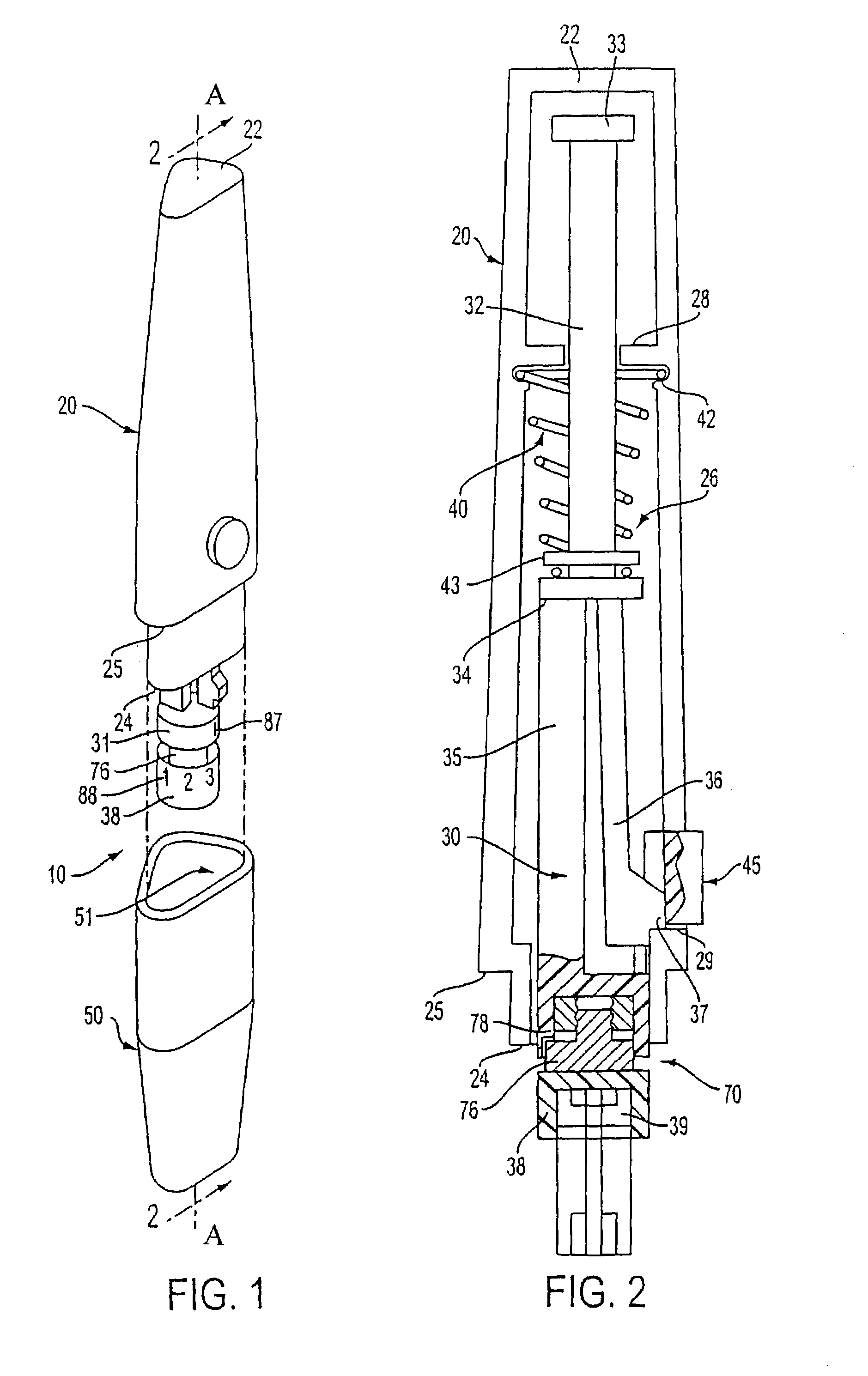
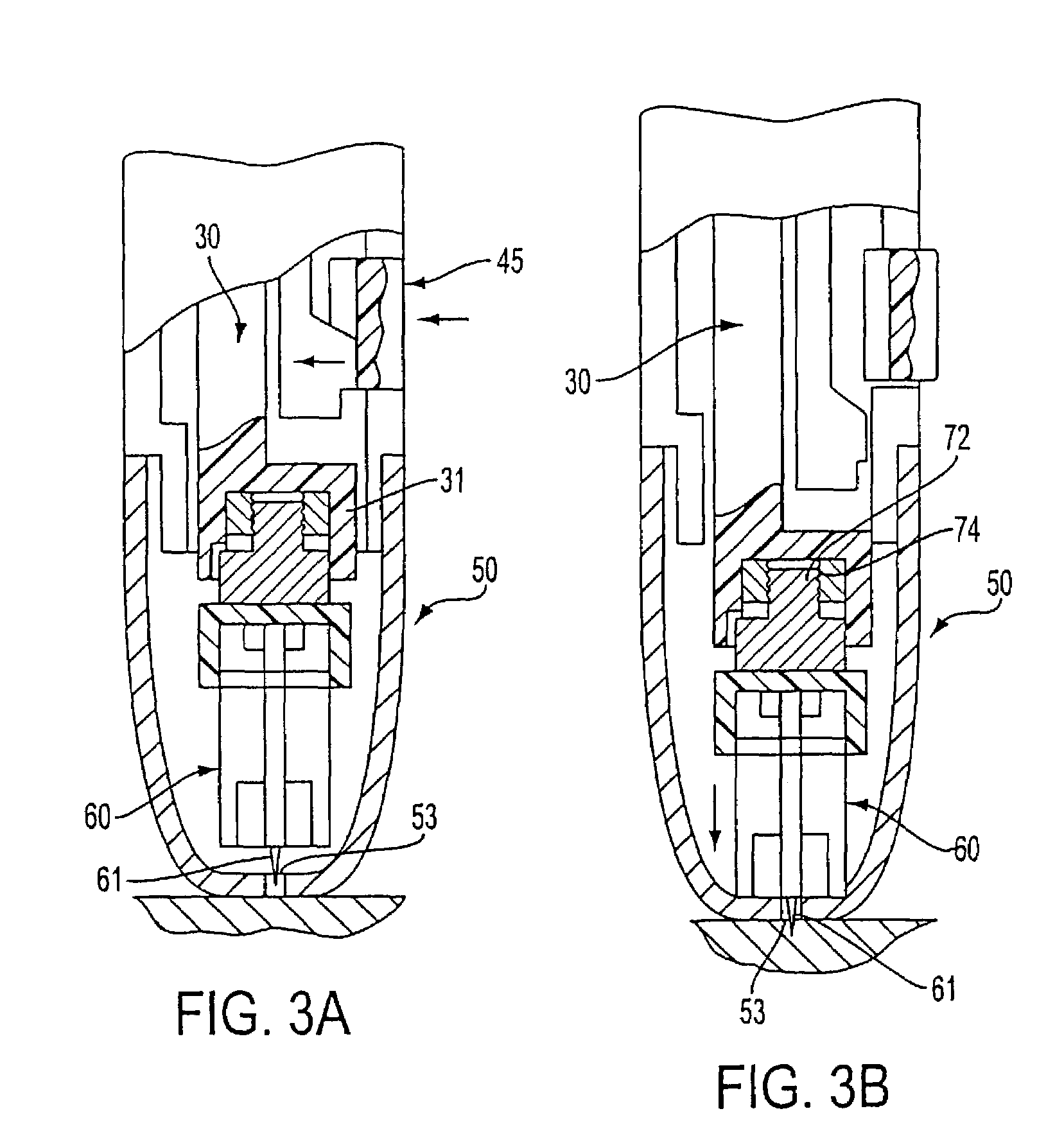
[0089]Before referring to the Figures, a broad overview of preferred aspects of the invention is provided. The lancet device includes an elongate housing, which is preferably triangular, adapted to fit within the user's hand. This housing includes a first end, which can be closed or open, an open second end, and an elongate channel therein which extends from...


PUM

PropertyMeasurementUnit
penetration depthaaaaaaaaaa
depth of penetrationaaaaaaaaaa
lengthaaaaaaaaaa

Abstract

Lancet device including a first housing. A first guide wall is disposed within the first housing. The first guide wall includes an opening. A cap removably mounted to the first housing. A needle holding member for holding a lancet. At least a portion of the needle holding member being able to move within the opening. A first spring for biasing the needle holding member toward an extended position. The first spring surrounding a portion of the needle holding member and being disposed between the first guide wall and a shoulder of the needle holding member. A movable trigger having a first position and a second position. A movable second housing including a proximal end, a distal end and a second guide wall arranged at the proximal end. The second guide wall including an opening. A portion of the needle holding member being able to move within the opening of the second guide wall. The second housing being configured to move the needle holding member to the retracted position when the second housing is moved away from the first housing. The proximal end of the second housing being configured to move axially within the distal end of the first housing. A second spring for biasing the second housing towards the first housing. The second spring surrounding a portion of the needle holding member and being disposed between the second guide wall and another shoulder of the needle holding member. At least a portion of the needle holding member is always retained within the first housing.

Description

CROSS-REFERENCE TO RELATED APPLICATIONS[0001]The present application is a continuation application of U.S. application Ser. No. 09 / 592,680, filed Jun. 12, 2000, now U.S. Pat. No. 7,175,641, which is a continuation of U.S. application Ser. No. 09 / 433,366, filed Nov. 3, 1999, which issued as U.S. Pat. No. 6,156,051 and which is a divisional application of U.S. application Ser. No. 09 / 095,902, filed Jun. 11, 1998, which issued as U.S. Pat. No. 6,022,366. The entire disclosures of U.S. application Ser. Nos. 09 / 592,680, 09 / 433,366 and 09 / 095,902 are considered as being part of the disclosure of the present application, and the entire disclosures of U.S. application Ser. Nos. 09 / 592,680, 09 / 433,366 and 09 / 095,902 are expressly incorporated by reference herein their entireties.[0002]The present application also expressly incorporates by reference herein the entire disclosure of U.S. application Ser. No. 09 / 095,905, entitled “Adjustable Length Member Such as a Cap of a Lancet Device for Adj...

Claims


Application Information

Patent Timeline
Patent Type & Authority Patents(United States)
IPC IPC(8): A61B17/34A61M5/00A61B5/15
CPCA61B5/1411A61B5/15019A61B5/15117A61B5/15132A61B5/150351Y10T29/53657A61B5/150022A61B5/150175A61B5/150198A61B5/150412A61B5/150503A61B5/15113A61B5/1513A61B5/1519
Inventor SCHRAGA, STEVEN
Owner STAT MEDICAL DEVICES
Why Eureka
Try Eureka