Laminate and method used for applying a design to a substrate

a technology of laminate and design, applied in the field of assembly, can solve the problems of difficult if not impossible repositioning, difficult to apply such decorative sheet materials to the desired location, and the challenge cannot always be met, so as to achieve the effect of quick and accurate application of decorative materials

Inactive Publication Date: 2007-12-25
3M INNOVATIVE PROPERTIES CO
View PDF13 Cites 18 Cited by
  • Summary
  • Abstract
  • Description
  • Claims
  • Application Information

AI Technical Summary

Benefits of technology

[0010]The present invention provides a laminate and a method using that laminate by which a person can quickly and accurately apply decorative material coated with aggressive pressure sensitive adhesive to a substrate in a desired pattern that for some types of applications is simpler, and more versatile than the prior art approaches described above.
[0011]According to the present invention there is provided a laminate for use in decorating a receptor surface such as the surface of a window or mirror. That laminate comprises an piece of decorative sheet material with a generally straight first edge surface, a layer of aggressive pressure sensitive adhesive on its rear surface, and a first release liner over a surface of that layer of adhesive opposite the decorative sheet material; and a flexible, temporary support tape comprising a backing and a layer of repositionable pressure sensitive adhesive on a second surface of the backing. A part of the layer of repositionable pressure sensitive adhesive adjacent a second edge surface of the backing is adhered to a front surface of the decorative material with a portion of the support tape projecting away from the first edge surface of the decorative strip. The repositionable pressure sensitive adhesive on that projecting portion of the support tape can be adhered to a receptor surface with the release liner on the decorative material laying along that receptor surface, and can be repositioned as needed to precisely position the decorative strip in a desired location along that receptor surface. Once so positioned, the flexible backing can be bent along a bend line along the first edge of the decorative material to separate the decorative material from the receptor surface so that the release liner can be manually removed. The layer of aggressive pressure sensitive adhesive on the decorative material can then be moved into contact with the receptor surface to adhere the decorative material against the receptor surface in the desired location, after which the temporary support tape can be peeled away from both the receptor surface and the decorative material.

Problems solved by technology

Applying such decorative sheet materials to a substrate in a desired location can be difficult because of the aggressive nature of the adhesive on the sheet materials.
Once that adhesive contacts a dry substrate such as a glass surface it is difficult if not impossible to reposition.
Thus those applying the decorative materials face the challenge of making an initial contact between the flexible decorative sheet materials and the substrate with the decorative sheet materials at a precise predetermined position, which challenge can not always be met, particularly by persons with little experience in applying the sheet materials.

Method used


Image

  • Laminate and method used for applying a design to a substrate
  • Laminate and method used for applying a design to a substrate
  • Laminate and method used for applying a design to a substrate

Examples


Embodiment Construction

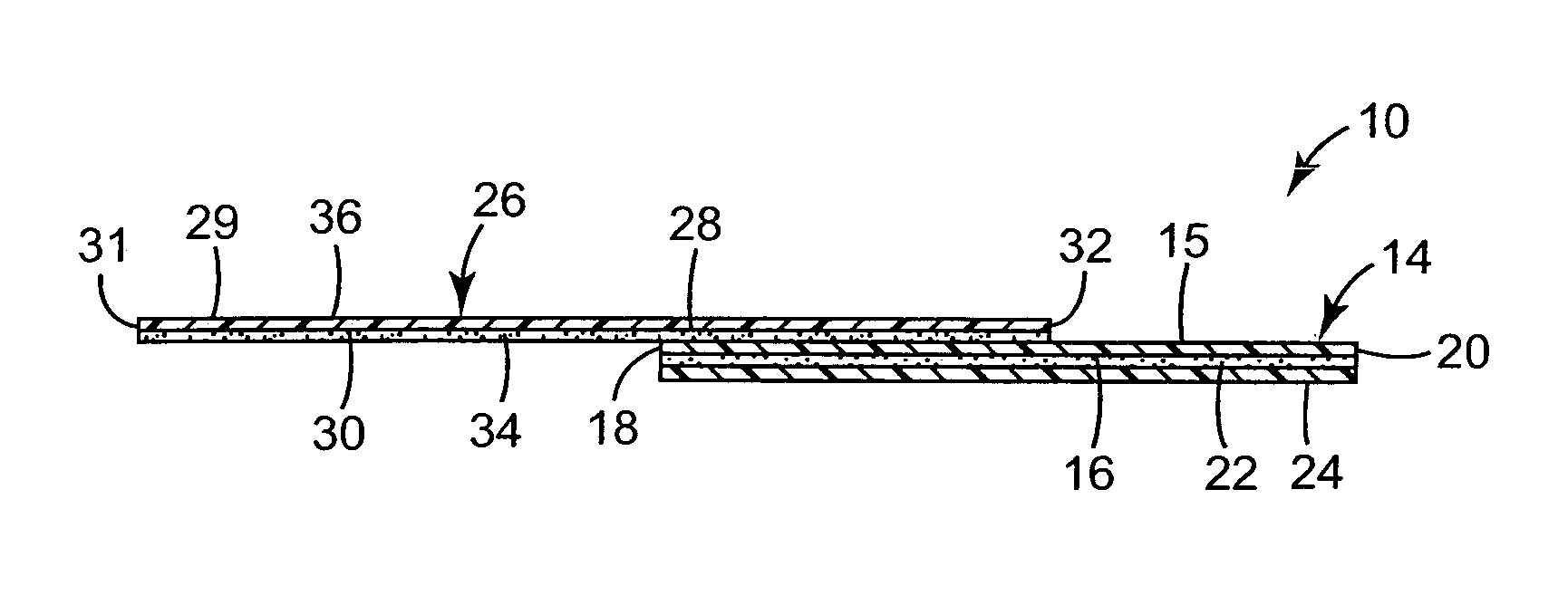
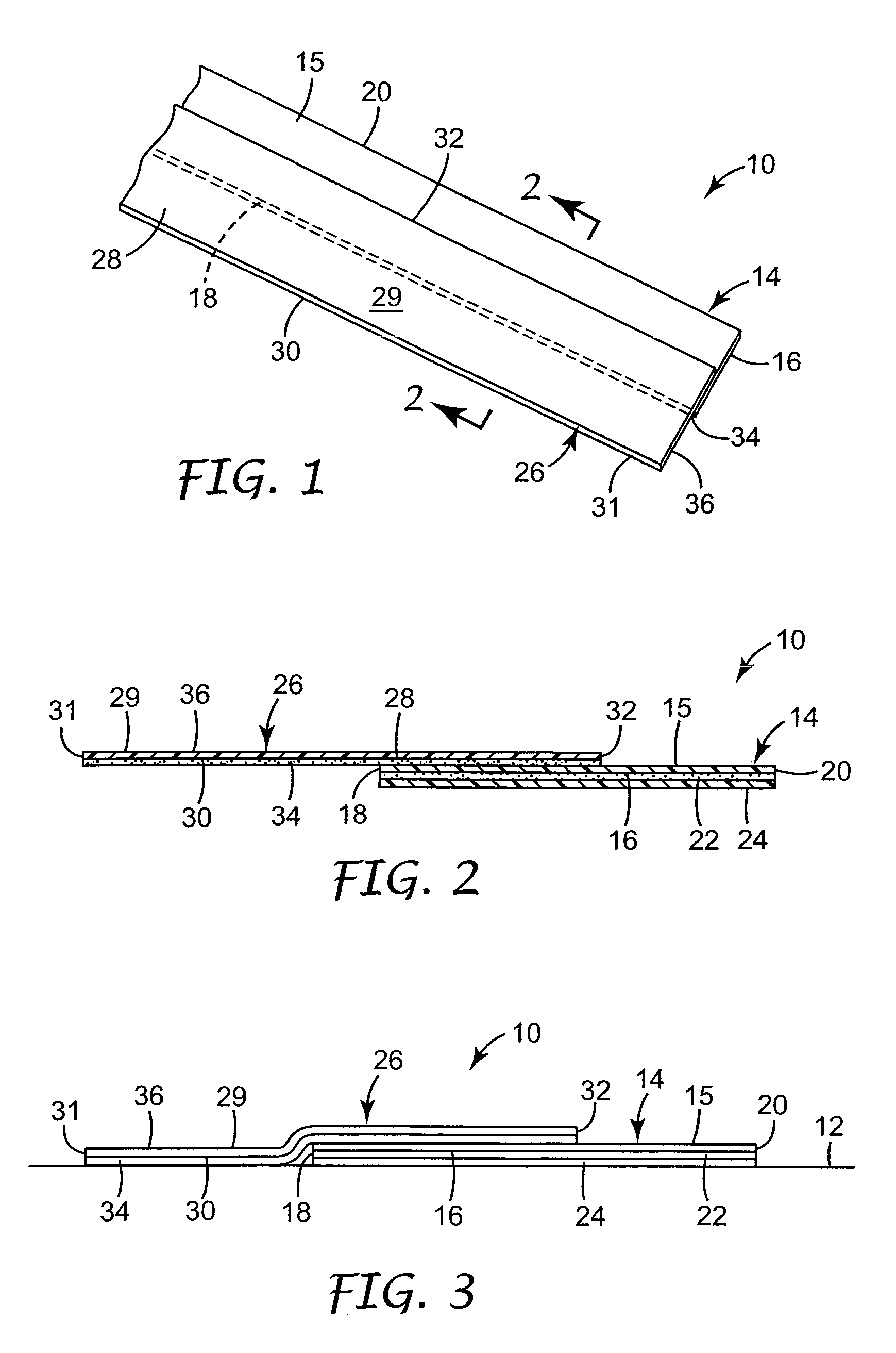
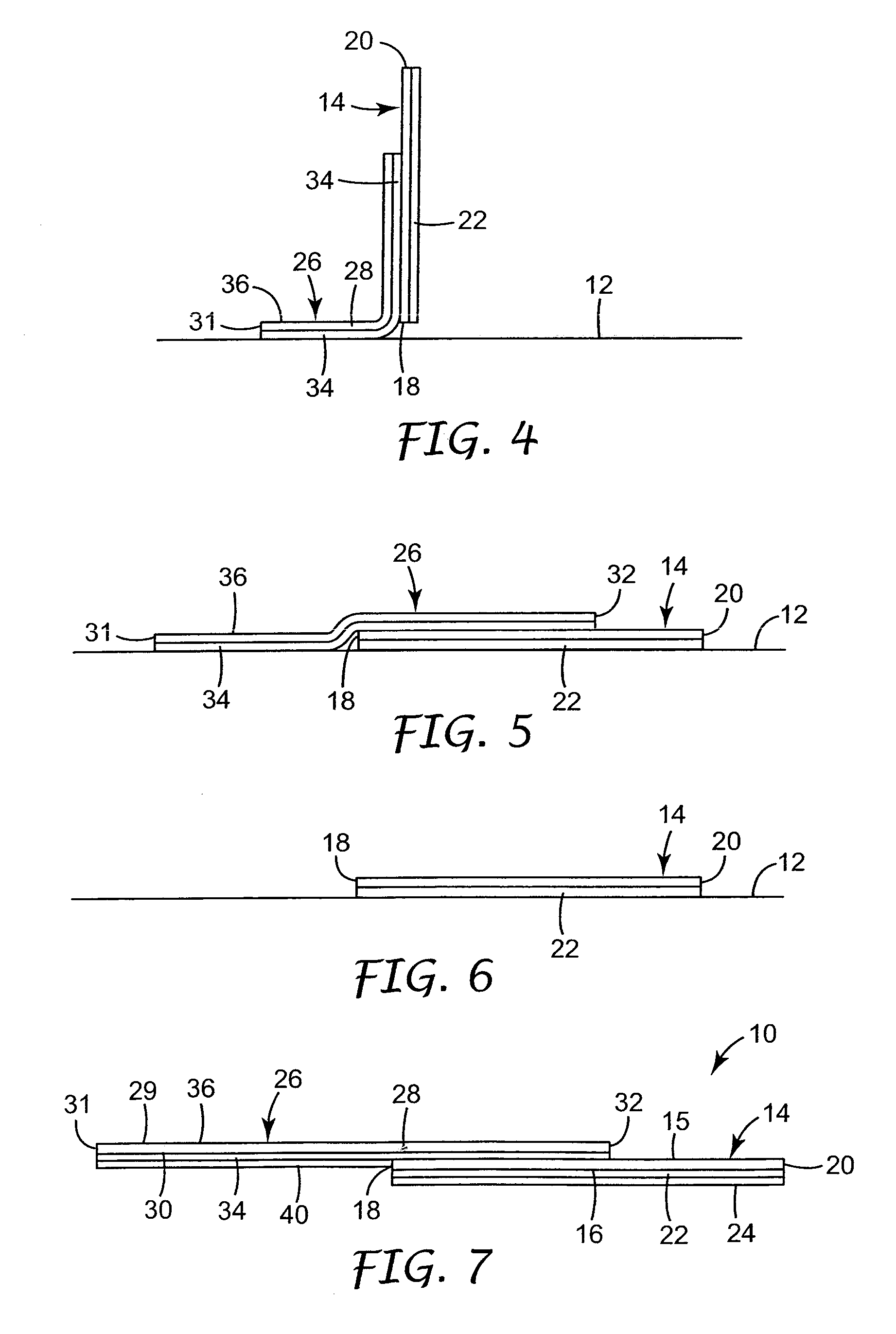
[0021]Referring now to FIG. 1 there is illustrated a first embodiment of a laminate 10 according to the present invention for use in decorating a receptor surface such as the surface 12 of a window or mirror which can be done using a method according to the present invention illustrated in FIGS. 3 through 6. The laminate 10 comprises a piece or elongate strip of decorative sheet material 14 having opposite front and rear surfaces 15 and 16 extending between a generally straight first edge surface 18 and an opposite second edge surface 20 of the decorative sheet material 14. A layer 22 of aggressive pressure sensitive adhesive is on the rear surface 16 of the decorative sheet material 14, and a first release liner 24 is over a surface of the layer of aggressive pressure sensitive adhesive opposite the decorative sheet material 14. The laminate 10 also includes a flexible, temporary support tape 26 comprising a flexible backing 28 having opposite first and second surfaces 29 and 30 ex...


PUM

PropertyMeasurementUnit
angleaaaaaaaaaa
anglesaaaaaaaaaa
anglesaaaaaaaaaa

Abstract

A laminate for use in decorating a receptor surface (e.g., a window) comprising a piece of decorative sheet material with a layer of aggressive pressure sensitive adhesive on its rear surface and a release liner over that layer of adhesive; and a flexible, temporary support tape comprising a backing and a layer of repositionable pressure sensitive adhesive on a second surface of the backing. A longitudinally extending part of the layer of repositionable pressure sensitive adhesive of the support tape is adhered to a front surface of the decorative strip, and an elongate portion of the support tape projects transversely away from a first edge surface of the decorative sheet material. The repositionable pressure sensitive adhesive on that projecting portion of the support tape can be adhered to a receptor surface with the first release liner on the decorative sheet material laying along that receptor surface, and can be repositioned as needed to precisely position the decorative sheet material in a desired location. Once so positioned, the flexible backing can be bent along a longitudinally extending bend line along the first edge of the decorative sheet material to separate the decorative sheet material from the receptor surface so that the first release liner can be manually removed. The decorative sheet material can then be moved back into contact with the receptor surface so that its layer of aggressive pressure sensitive adhesive adheres the decorative sheet material against the receptor surface in the desired location, after which the temporary support tape can be peeled away.

Description

FIELD OF THE INVENTION[0001]The present invention relates to assemblies and methods used for applying adhesive coated decorative sheet material to substrates such as sheets of glass.DESCRIPTION OF THE RELATED ART[0002]Several decorative sheet materials are known that can be adhered to substrates such as sheets of glass to decorate the substrate. Typically these materials have an outer major surface that is viewed to see the decorative aspect of the materials, a layer of aggressive pressure-sensitive adhesive selected to form strong bonds to glass on an opposite rear surface, and a low-adhesion release liner over the surface of the adhesive opposite the sheet material. One such decorative sheet material is a length of film that has grooves, vapor coating and / or other structure along its outer major surface so that the decorative film visually simulates decorative glass, such as glass with a single bevel, beveled edges, or with a central groove along its length (e.g., a V shaped groov...

Claims


Application Information

Patent Timeline
Patent Type & Authority Patents(United States)
IPC IPC(8): B32B9/00B26B29/00B44C1/00B44C1/10B44C1/17B44F1/06
CPCB44C1/105B44F1/06Y10S428/914Y10T428/1486Y10T428/149Y10T428/31Y10T428/1495Y10T428/14Y10T156/1051Y10T428/1481
Inventor PITZEN, JAMES F.
Owner 3M INNOVATIVE PROPERTIES CO
Why Eureka
Try Eureka