Image forming apparatus with another secondary power supply

a technology power supply, which is applied in the direction of electrographic process apparatus, instruments, optics, etc., can solve the problems of low cost, inability to operate directly, and power consumption of image forming apparatus, so as to prevent temperature rise and moisture condensation

Active Publication Date: 2007-12-25
RICOH KK
View PDF13 Cites 17 Cited by
  • Summary
  • Abstract
  • Description
  • Claims
  • Application Information

AI Technical Summary

Benefits of technology

[0023]Accordingly, it is a general object of the present invention to provide an image forming apparatus in which the secondary power supply and the fixing unit are disposed close to each other, and temperature rise and moisture condensation can be prevented.
[0027]In the case of an image forming apparatus according to the present invention, since the secondary power supply is disposed at a position at which the heat generated for the fixing unit does not affect the secondary power supply much, the capacitor configuring the secondary power supply is prevented from being heated to an excessive temperature by the heat. Because the secondary power supply is disposed close to the fixing unit, the wire can be made short, and the wiring becomes easy. At the same time, the electric power loss caused by the wire can be reduced. According to this arrangement, the durability and the efficiency of fixation can be improved. It is possible to provide a fixing unit of which rise time is very short without providing additional space in which the secondary power supply is disposed, and making the image forming apparatus larger. Accordingly, the durability of the secondary power supply and the efficiency of the fixing unit can be improved, and at the same time, the image forming apparatus can be made compact.
[0028]The insulation member prevents the capacitor from being heated to an excessive temperature by the heat generated by the fixation part. At the same time, the insulation member prevents moisture from being condensed. It protects the secondary power supply from dust generated by the image forming apparatus, and prevents a user from touching the secondary power supply. Furthermore, since the secondary power supply is made detachable, a storage unit can be easily set up, recovered, and maintained. It is possible to add the storage unit afterward to an image forming apparatus that has no secondary power supply. The image forming apparatus of which rise time is short using the secondary power supply can be configured. Since the discharging unit is provided, the charge charged in the capacitor can be safely discharged. This makes the setup, recovery, and maintenance of the secondary power supply safe. In addition, since the switch is provided that turns on and off the connection between the secondary power supply and the cooling unit, the charge charged in the capacitor can be safely discharged, and this makes the setup, recovery, and maintenance of the secondary power supply safe. Since the secondary power supply is provided with the cooling unit, the capacitor can be prevented from being heated to an excessive temperature by the heat generated by the fixation part. At the same time, the cooling unit can avoid moisture condensation.

Problems solved by technology

Especially, electrophotography is widely employed for image forming apparatuses, because it can form an image of high quality at high speed, but its cost is low.
The heating of the metal roller up to the operable temperature may take a long time (hereinafter, referred to as a rise time), for example, several minutes due to the high heat capacity of the metal roller.
However, even while being kept at a temperature not as high as the operating temperature, the image forming apparatus consumes power that is not directly needed for its operation.
In Japan, the amended power saving law becomes more severe.
The image forming apparatus becomes unuseful.
However, this method is practical only if there are two separate power adaptors close to the image forming apparatus.
In addition, if a great current is discharged, the life of a rechargeable battery is shortened.
Furthermore, since the rechargeable battery of high capacity requires some hours to be charged, it is not practical to use the rechargeable battery for applications that require repeated charging and discharging within a day.
Accordingly, the rechargeable battery cannot realize a practical secondary power supply.
It is difficult to increase the maximum current.
In this case, even if a certain number of cells are enough to provide the halogen heater with sufficient energy, additional cells that are excessive energy-wise also need to be provided in order to increase the output voltage.
This increases the cost of the power supply, and excessively increase the volume thereof.
However, if the halogen heater is connected to the high-capacity capacitor in parallel, and a great current is flowed, wiring may cause a great loss as Joule heat.
However, thick wire makes wiring in the image forming apparatus very difficult.
The thick wire requires large space, and makes assembly difficult.
In the case of an electrophotography type image forming apparatus, the internal temperature often rises to 70-80° C. due to heat generated by the fixing unit and heat generated by the recent increase in power consumption of electric circuits.
For example, the operating temperature of a gold capacitor manufactured by Matsushita Electric Industries KK is about −25° C.-+60° C. The operating temperature of Lithium Ion Batteries and Nickel Hydrogen Batteries of the same manufacturer is, in the case of charging, 0° C.-+45° C., and in the case of discharging, −10° C.-+60° C. In addition, the durability of the high-capacity capacitors is degraded at an excessively high temperature.
The high-capacity capacitor may be degraded due to the heat generated by the fixing unit, and as a result, the durability of the image forming apparatus may be degraded.
The condensed moisture, if it forms water droplet and enters the circuit of the secondary power supply, may cause a short circuit or leak.
In the case in which a non-water electric double layer capacitor using organic solvent as electrolyte is used as a charging element, if the water enters the capacitor cells through a relief valve or a junction part, the performance is considerably degraded.
Since the secondary batteries use organic solvent, the entering of water into the secondary batteries cause considerable degrading of performance.

Method used


Image

  • Image forming apparatus with another secondary power supply
  • Image forming apparatus with another secondary power supply
  • Image forming apparatus with another secondary power supply

Examples


Embodiment Construction

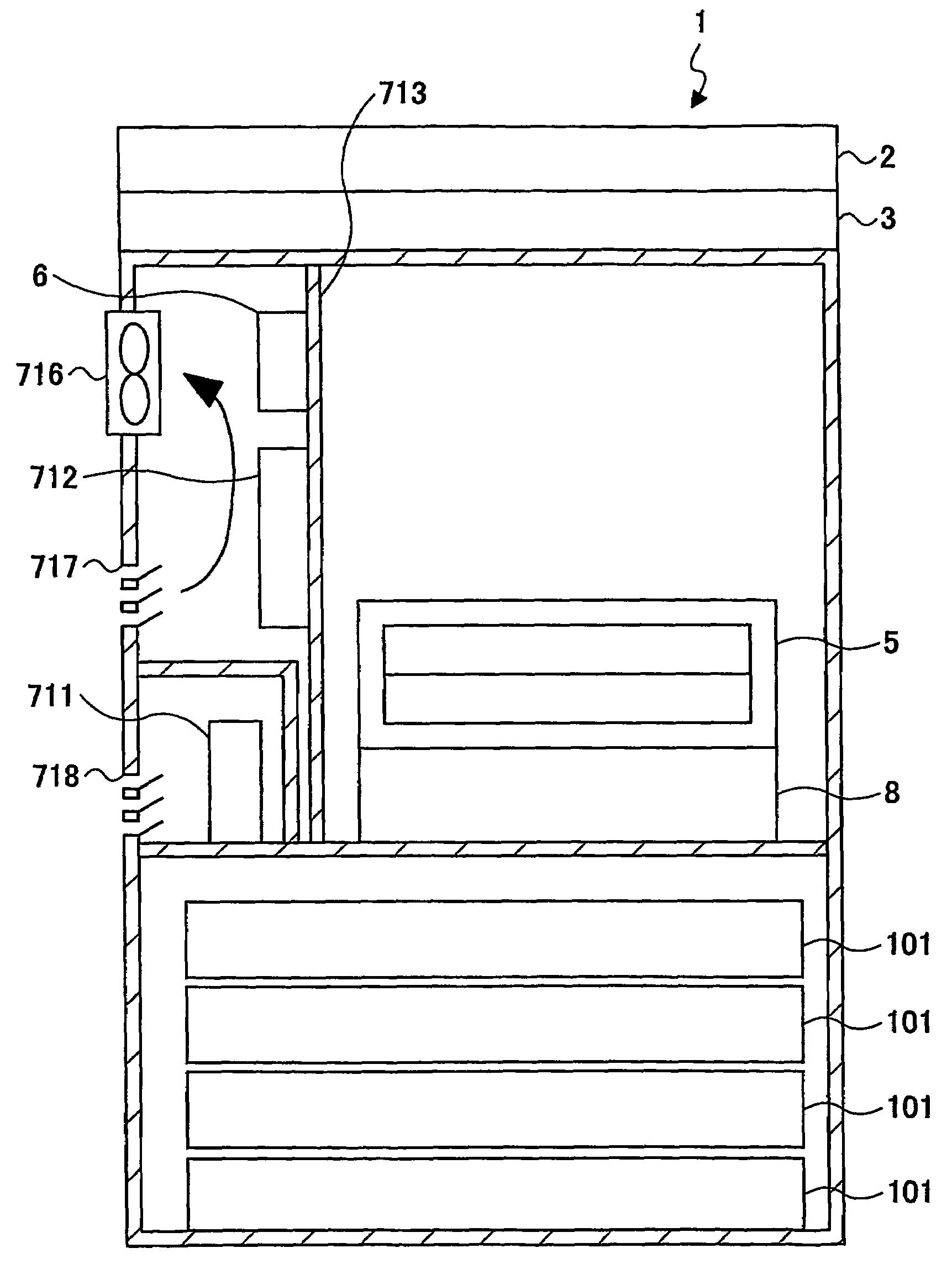
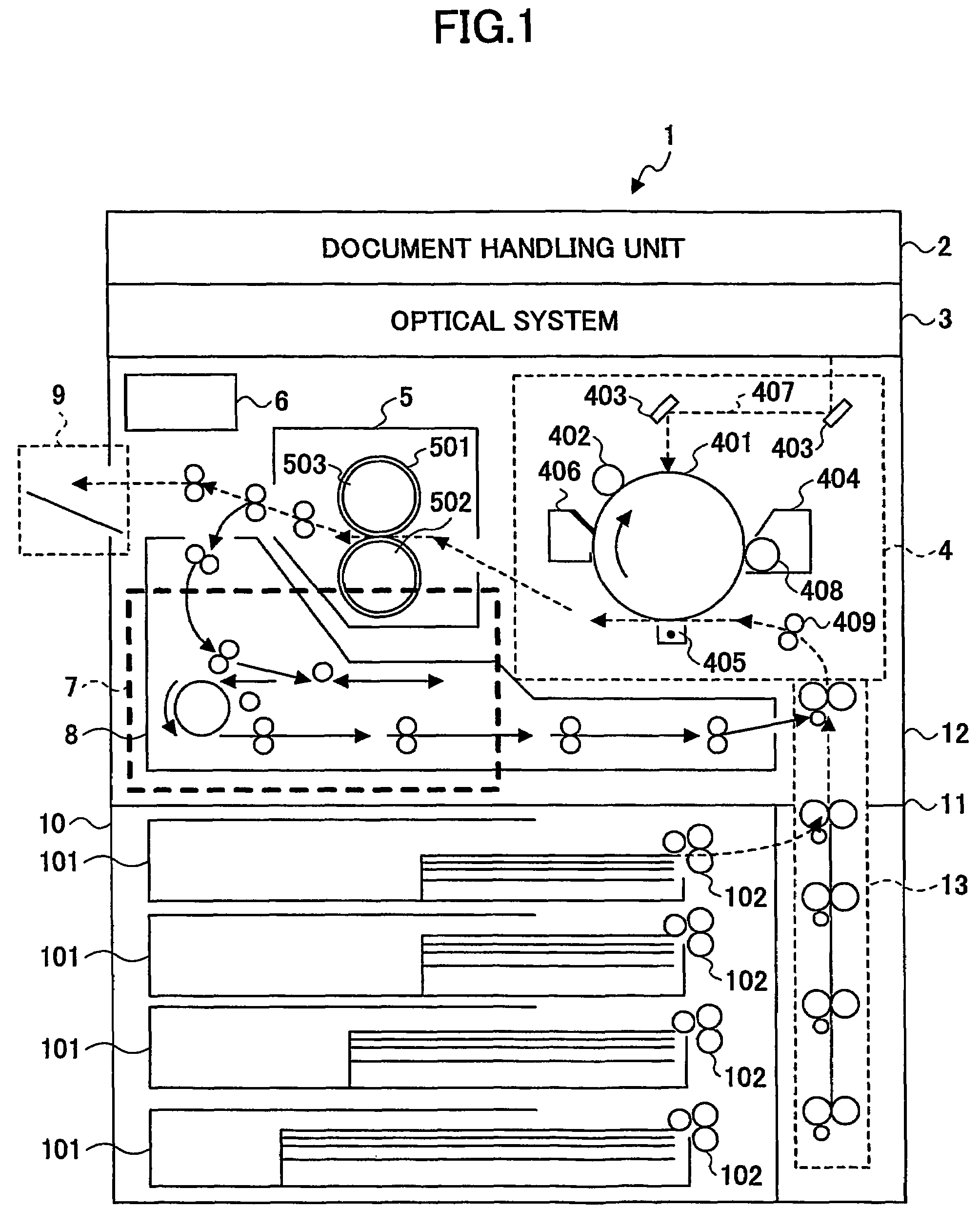
[0045]The configuration of an image forming apparatus 1 according to a first embodiment is shown in FIG. 1. The image forming apparatus 1 is tall so that a user can dispose it on the floor and use it comfortably. The image forming apparatus 1 is provided with the following: a document handling unit 2 for transporting documents; an optical system 3 for applying light to the document transported by the document handling unit 2 and reading images; an image forming unit 4 for transferring the image read by the optical system 3 to a recording member such as paper; a fixing unit 5 for fixing the transferred image to the recording member; a main power supply 6 for supplying electric power to the entire apparatus; a secondary power supply 7 charged by the main power supply 6 for supplying electric power to the fixing unit 5; a reversing unit 8 for reversing the front and back of the recording member when an image is transferred and fixed on the front and the back of the recording member; a ...


PUM


Abstract

An image forming apparatus including: a fixing unit; a main power supply that provides a portion of the heaters with voltage; and a secondary power supply that provides another portion of the heaters connected to the portion of the heaters in parallel with power provided by the main power supply. The secondary power supply is disposed below and in the neighborhood of the fixing unit. The secondary power supply may be disposed between a side face of a chassis of the image forming apparatus and the fixing unit, or at an exterior of the chassis of the image forming apparatus on the side face of the chassis. The secondary power supply can be prevented from being heated by the fixing unit.

Description

TECHNICAL FIELD[0001]The present invention generally relates to an image forming apparatus, and more particularly, to a fixing unit for fixing a toner image used for an image forming apparatus such as an electrophotographic copier, printer, and facsimile machine, for example.BACKGROUND ART[0002]Various methods to form an image on a recording medium such as plain paper and overhead projection film have been realized, and are used for copiers, printers, and facsimile machines, for example. Especially, electrophotography is widely employed for image forming apparatuses, because it can form an image of high quality at high speed, but its cost is low.[0003]When an image is formed using electrophotography, generally, a toner image that has not been fixed yet is formed on a recording medium. Then, a fixing unit applies heat and pressure to the toner image thereby to fix the toner image on the recording medium. A heat roller method is widely used for the application of the heat and the pres...

Claims


Application Information

Patent Timeline
Patent Type & Authority Patents(United States)
IPC IPC(8): G03G15/00G03G21/20G03G21/00G03G15/20
CPCG03G15/80G03G2215/00978G03G21/1685G03G2215/20
Inventor MATSUSAKA, SUSUMU
Owner RICOH KK
Why Eureka
Try Eureka