Network storage system and handover method between plurality of network storage devices

a network storage and network storage technology, applied in the field of network storage system and handover method between a plurality of network storage devices, can solve the problems of inability to specify the position of the file directly, the shortage of network storage capacity, and the inability of the storage device to specify

Active Publication Date: 2007-12-25
GOOGLE LLC
View PDF19 Cites 30 Cited by
  • Summary
  • Abstract
  • Description
  • Claims
  • Application Information

AI Technical Summary

Benefits of technology

[0017]Accordingly, an object of the present invention is to provide a network storage system and a handover method between a plurality of network storage devices that, even when access to a file that has not been transferred to a second network storage device is requested, make it possible to specify the file immediately on the file system of a first network storage device that stores the file, acquire data from the first network storage device and supply the data to a client, and transfer (hand over) file sharing services from the first network storage device to the second network storage device in a relatively short period.
[0018]An object of the present invention is to provide a network storage system and handover method between a plurality of network storage devices that makes it possible to implement a data transfer in file units between network storage devices in a relatively short period without changing the stored content of the first network storage device in which the file is stored and without adding special functions to the first network storage device. Further objects of the present invention will become apparent from the description of the subsequent embodiments.
[0019]In order to resolve the above problem, the network storage system of the present invention has a constitution that makes it possible to directly specify a file that has not been transferred from the first network storage device (existing network storage device) to the second network storage device (newly installed network storage device) on the first network storage device and of transferring data in file units. Accordingly, the network storage system of the present invention is able to commence file sharing services before transferring the data of the whole file tree.
[0032]The file tree generation unit is able to generate the second file tree by associating transfer state information, which indicates whether a file on the first network storage device has been transferred to a predetermined location on the second file tree, with the structure of the second file tree. The file tree structure can be shown by the method by which each element constituting the tree (files, directories, and so forth) is connected. Therefore, information that indicates whether the substance (data) of the file has been transferred to the second network storage device (transfer state information) is associated with a file, which is one element constituting the structure of the file tree. That is, information indicating that data of the file has not yet been transferred is associated with the location in which the data of the file should be stored in future. As a result, the file system of the second network storage device is able to judge instantly whether the file has been transferred by referencing the transfer state information.

Problems solved by technology

Because of the volume of data to be managed by such organizations increases on a daily basis, the administrator of a network storage system is, before long, confronted by a shortage of network storage capacity.
It is not possible to specify directly the position of the file in the file tree by means of file identification information alone.
Further, the file identification information basically functions effectively on the file system that issued the file identification information and cannot be used on a different file system.
Therefore, even when file access has been requested by the client, the newly installed network storage device is unable to specify the requested file in cases where a file is designated by using file identification information issued by a file system other than the file system of the newly installed network storage device or in cases where the requested file does not exist on the newly installed network storage device.
That is, the file system of the newly installed network storage device is unable to specify where the requested file is located in the existing network storage device on the basis of the file identification information issued by the file system of the existing network storage device alone and is therefore unable to access the substance of the requested file.
Therefore, in the technology appearing in Japanese Patent Application Laid Open No. 2004-46661, access by the newly installed network storage device to a file that has not already been transferred from the existing network storage device to the newly installed network storage device is difficult.
Hence, in the case of the technology appearing in Japanese Patent Application Laid Open No. 2004-46661, it is not enough to simply copy the file tree structure of the existing network storage device to the newly installed network storage device beforehand.
Therefore, in the case of the technology appearing in Japanese Patent Application Laid Open No. 2004-46661, file sharing services cannot be restarted during the interval up until the data transfer of the whole file tree from the existing network storage device to the newly installed network storage device is complete.
As a result, replacement of the network storage device takes a long time.
Further, with the technology appearing in Japanese Patent Application Laid Open No. 2004-46661, the data must have already been transferred before services are restarted, meaning that data cannot be transferred while file sharing services are being provided to the client.
However, although this virtual unification is significant from the perspective of the practical application of assets, the existing network storage device cannot be completely replaced with a newly installed network storage device.
Therefore, an old file group that has been stored in the existing network storage device must be supplied by the existing network storage device whose access performance is relatively poor, and hence the response of the whole system drops.
Further, the old-type network storage device with inferior performance must be maintained indefinitely, which increases the maintenance and running costs of the system.

Method used


Image

  • Network storage system and handover method between plurality of network storage devices
  • Network storage system and handover method between plurality of network storage devices
  • Network storage system and handover method between plurality of network storage devices

Examples


first embodiment

1. First Embodiment

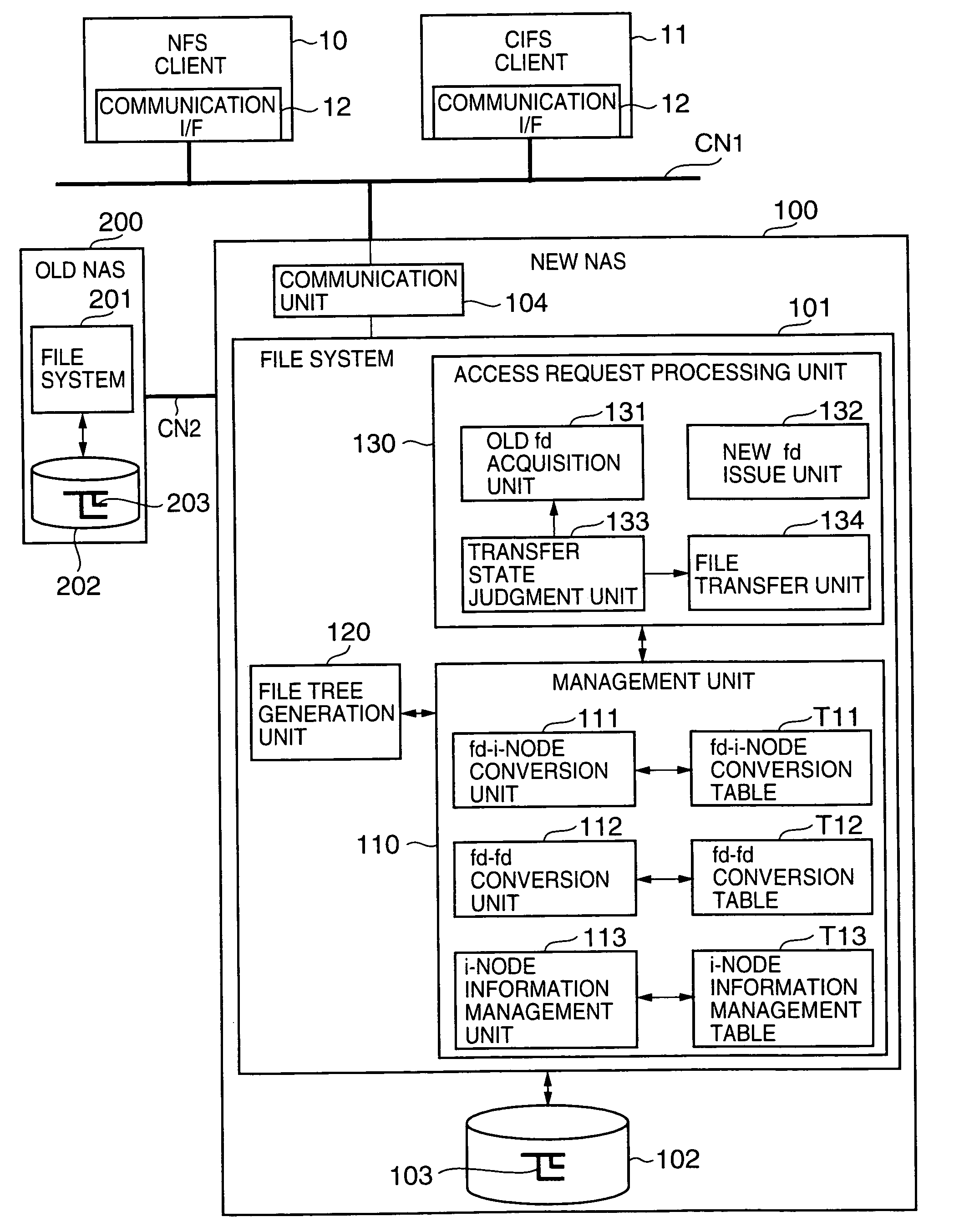
[0089]FIG. 3 is a schematic block diagram in which the focus is on the hardware constitution of the network storage system. The network storage system can be constituted comprising a plurality of clients 10, 11, a network storage device 20, and a communication network CN1 that mutually connects the network storage device 20 and the respective clients 10 and 11, as described subsequently.

[0090]The clients 10 and 11 are programs installed on a computer device for using file sharing services (NAS services) provided by the network storage device 20. Here, for example, the client 10 is an NFS (Network File System, registered trademark) client that provides an NFS on a UNIX (registered trademark) OS. Further, the client 11 is a CIFS (Common Internet File System, registered trademark) client that provides a CIFS on a Windows (registered trademark) OS, for example. NFS and CIFS are file access protocols that run on TCP / IP (Transmission Control Protocol / Internet Protocol),...

second embodiment example

2. Second Embodiment Example

[0205]The second embodiment example will be described on the basis of FIGS. 18 and 19. This embodiment example is characterized by the fact that the construction of the association between the old fd and new fd is started when the file tree structure is transferred from the old NAS 200 to the new NAS 100.

[0206]FIG. 18 is an outline flowchart showing the procedure of the overall operation of this embodiment example. The overall operation shown in FIG. 10 differs with respect to P23 and P28. P21 and P22 correspond to P1 and P2 in FIG. 10, P24 to P27 correspond to P3 to P7 in FIG. 10, and P29 to P31 correspond to P9 to P11 in FIG. 10, and hence a repetitive description of the former steps is omitted here.

[0207]When the file tree structure is copied from the old NAS 200 to the new NAS 100, the old fd managed by the old NAS 200 and the i-node number managed by the new NAS 100 are associated and saved in P23. Subsequently, in P28, an association is made between...

third embodiment example

3. Third Embodiment Example

[0211]A third embodiment example will now be described with reference to FIGS. 21 and 22. This embodiment example is characterized in that the file tree structure is copied from the old NAS 200 to the new NAS 100 in accordance with file access by the clients and an association between the old fd and new fd is constructed. That is, this embodiment example permits a transfer from the old NAS 200 to the new NAS 100 in cases where the clients 10, 11 are in an operating state.

[0212]FIG. 21 is a flowchart showing an outline of the overall processing of this embodiment example. First, the network configuration information of the old NAS 200 is handed over to the new NAS 100 (S201) and the old NAS 200 terminates the provision of services to the clients 10, 11 (S202). The system administrator then connects the old NAS 200 and new NAS 100 directly (S203) and allows the task of providing NAS services to be transferred from the old NAS 200 to the new NAS 100 (S204).

[0...


PUM


Abstract

The present invention shortens service termination times and permits rapid transfers. A file tree with the same structure as that of the file tree of a first NAS is formed in a second NAS beforehand. File data is not transferred to the tree. The second NAS saves an association between a file descriptor fd1 managed by the first NAS and fd2 managed by the second NAS. Services for a client are restarted when the transfer of the tree structure is complete. When the client requests access to a desired file by designating fd2, the second NAS converts fd2 to fd1 and requests file data from the first NAS. When the first NAS reads the file data, the second NAS stores the file data in a predetermined location and supplies the file data to the client. In cases where the client desires file access once again, the second NAS reads the transferred file data and supplies same to the client.

Description

CROSS-REFERENCE TO RELATED APPLICATIONS[0001]This application relates to and claims priority from Japanese Patent Application No. 2004-217031 filed on Jul. 26, 2004, the entire disclosure of which is incorporated herein by reference.BACKGROUND OF THE INVENTION[0002]The present invention relates to a network storage system and a handover method between a plurality of network storage devices.[0003]A network storage device is a storage device that is connected to a communication network such as the Internet or a LAN that is shared by a plurality of computers. NAS (Network Attached Storage) or similar is a known example of a network storage device. In organizations such as enterprises, municipalities, or schools, one or a plurality of network storage devices are introduced to construct a network storage system in order to manage enormous amounts of data.[0004]Because of the volume of data to be managed by such organizations increases on a daily basis, the administrator of a network stor...

Claims


Application Information

Patent Timeline
Patent Type & Authority Patents(United States)
IPC IPC(8): G06F17/30
CPCG06F17/30067Y10S707/99955H04L67/1097G06F16/10
Inventor MUROTANI, AKIRA
Owner GOOGLE LLC
Why Eureka
Try Eureka