Hammer drill with a mode changeover mechanism

a technology of mode changeover and hammer drill, which is applied in the direction of manufacturing tools, portable power-driven tools, and hammering. it can solve the problem of complex challenges

Active Publication Date: 2008-01-01
BLACK & DECKER INC
View PDF65 Cites 128 Cited by
  • Summary
  • Abstract
  • Description
  • Claims
  • Application Information

AI Technical Summary

Problems solved by technology

Manufacturers of power tools are constantly challenged to provide power tools that easily operated yet provide the users with diverse functionality.
The challenge becomes more complex where a given power tool is to be marketed globally, as differences in the language and culture of various markets will tend to discourage the marking of the power tool with complex symbols or words.

Method used


Image

  • Hammer drill with a mode changeover mechanism
  • Hammer drill with a mode changeover mechanism
  • Hammer drill with a mode changeover mechanism

Examples


Embodiment Construction

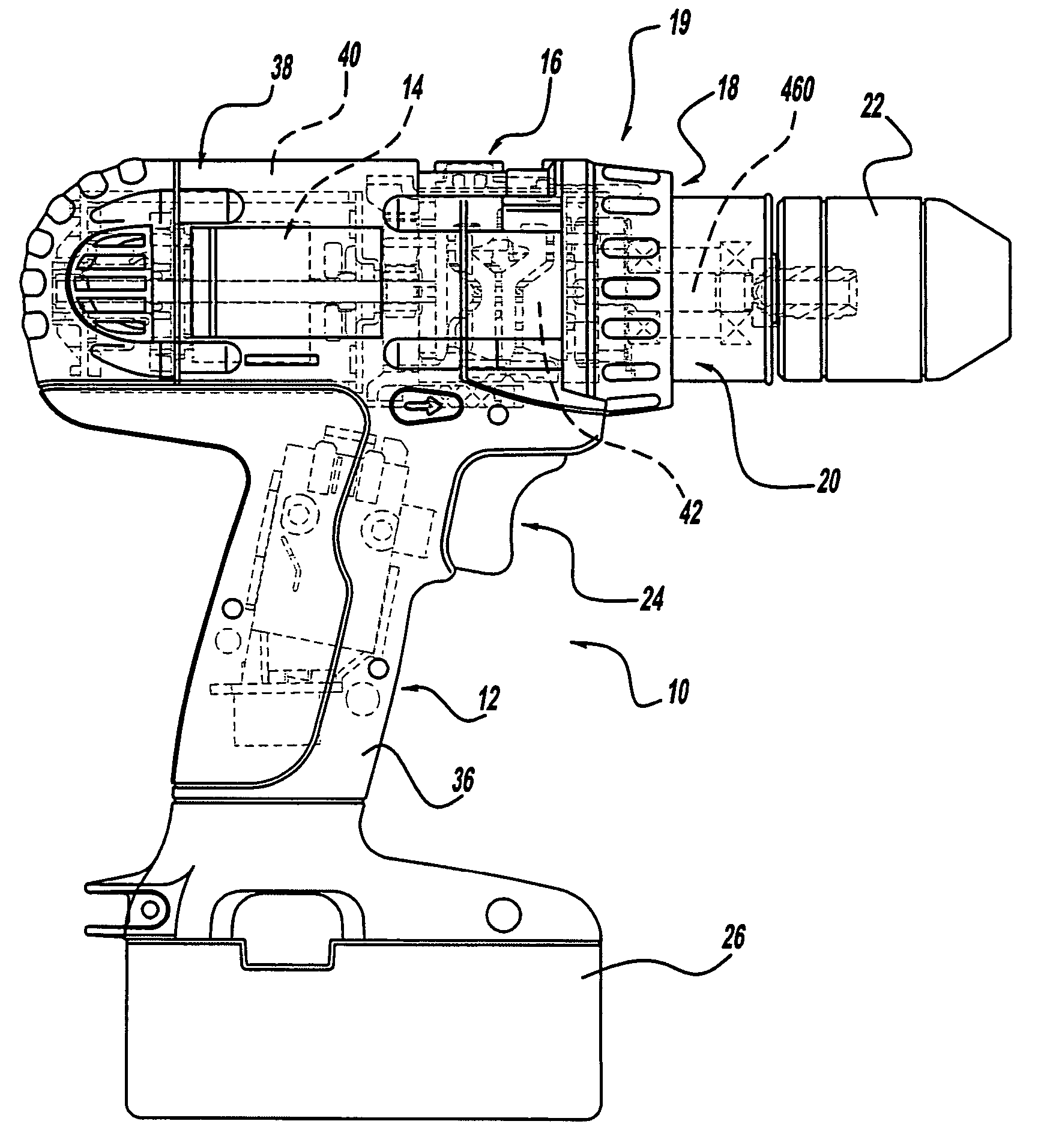
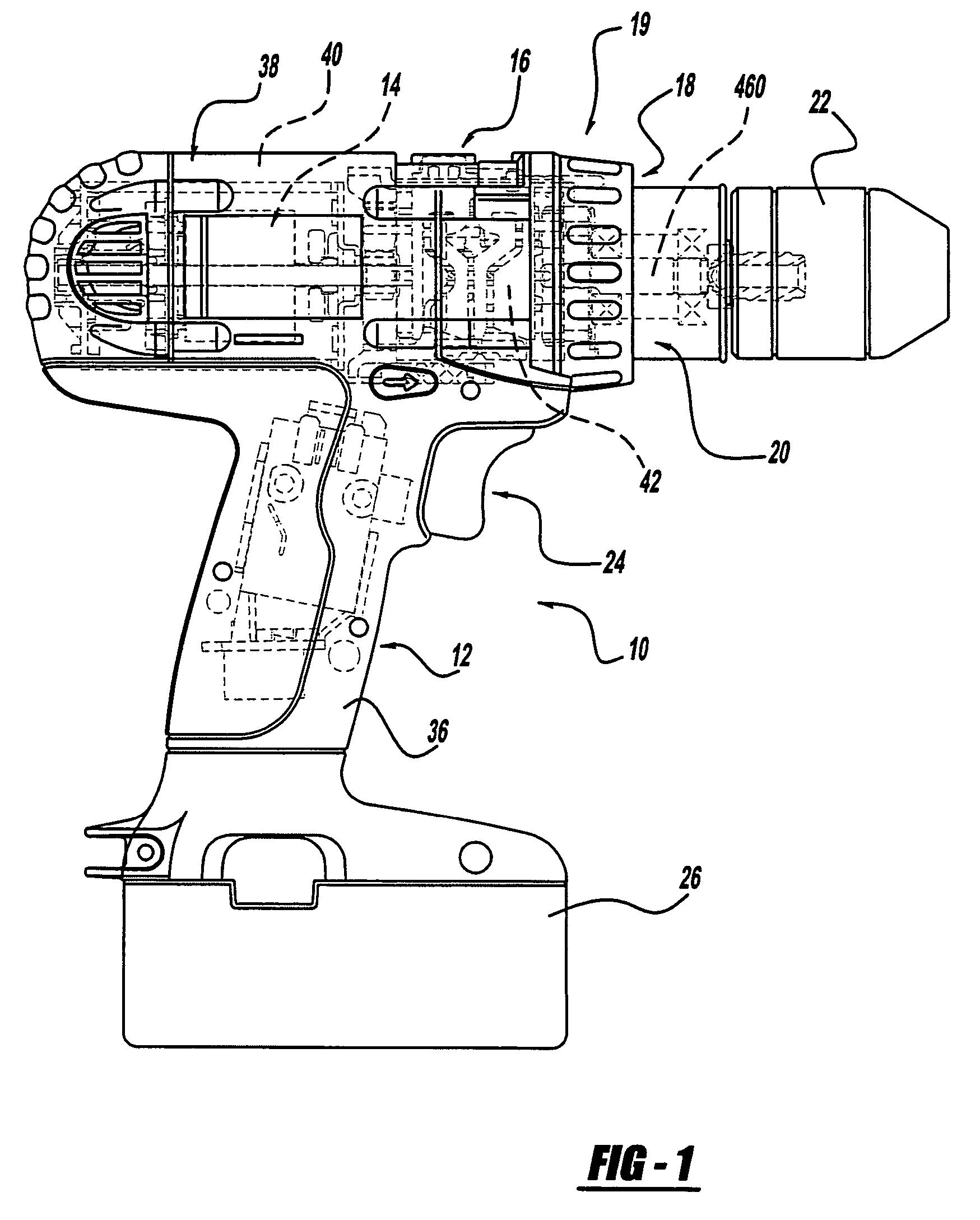
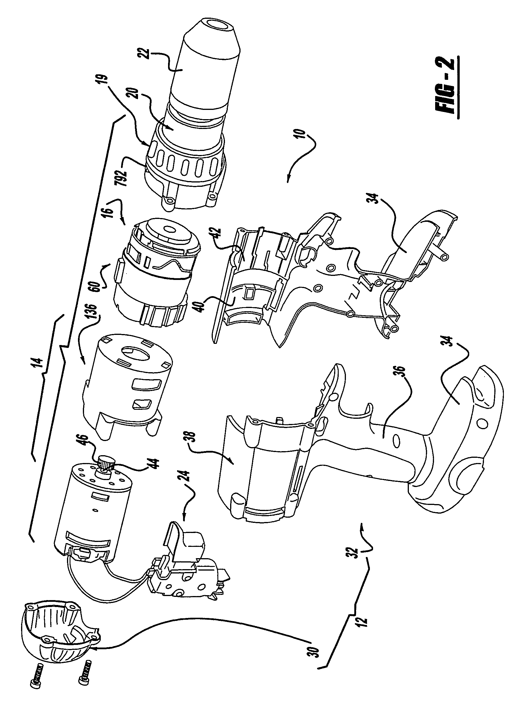
[0050]With reference to FIGS. 1 and 2 of the drawings, a hammer drill / driver constructed in accordance with the teachings of the present invention is generally indicated by reference numeral 10. As those skilled in the art will appreciate, the hammer drill driver 10 may be either a cord or cordless (battery operated) device and can have a housing 12, a motor assembly 14, a multi-speed transmission assembly 16, a clutch mechanism 18, a percussion or hammer mechanism 19, an output spindle assembly 20, a chuck 22, a trigger assembly 24 and a battery pack 26. Those skilled in the art will understand that several of the components of hammer drill / driver 10, such as the chuck 22, the trigger assembly 24 and the battery pack 26, are conventional in nature and need not be described in significant detail in this application.

[0051]Reference may be made to a variety of publications for a more complete understanding of the operation of the conventional features of hammer drill / driver 10. One ex...


PUM


Abstract

A hammer drill / driver with a motor having an output member, a planetary transmission, a clutch assembly and a clutch bypass. The planetary transmission, which includes a ring gear, receives rotary power from the output member and produces a rotary output. The clutch assembly has a clutch profile, which is coupled to the ring gear, and a first pin assembly having a first follower, a first pin member and a first spring that biases the first follower into contact with the clutch profile. The clutch bypass has a bypass profile, which is coupled to the ring gear, and second pin assembly having a second follower, a second pin member, a second spring, which biases the second follower away from the bypass profile, and a third spring, which biases the second follower away from the second pin member. A method for operation of a hammer drill / driver is also provided.

Description

CROSS-REFERENCE TO RELATED APPLICATIONS[0001]This application claims the benefit of U.S. Provisional Patent Application Ser. No. 60 / 655,768 entitled “Hammer Drill With A Mode Changeover Mechanism” and filed Feb. 24, 2005.INTRODUCTION[0002]The present invention relates generally to hammer drill drivers and more particularly, to systems for changing between a screwdriver mode, which provides a rotary output whose torque is limited by a clutch assembly, a drill mode, which provides a rotary output whose torque is not limited by a clutch assembly, and a hammer drill mode, which provides a rotary and percussive output whose torque is not limited by a clutch assembly.[0003]Manufacturers of power tools are constantly challenged to provide power tools that easily operated yet provide the users with diverse functionality. The challenge becomes more complex where a given power tool is to be marketed globally, as differences in the language and culture of various markets will tend to discourag...

Claims


Application Information

Patent Timeline
Patent Type & Authority Patents(United States)
IPC IPC(8): B25F5/00F16H37/08
CPCB25B21/00B25B23/14B25B23/141B25D11/106B25D16/003B25D16/006B25D2216/0023B25D2216/0038B25D2216/0092B25D2250/101B25D2250/165B25D2250/221
Inventor JENNER, CHERYLDEBELIUS, STEPHEN A.SCHELL, CRAIG A.PUZIO, DANIELCEROLL, WARREN A.GEHRET, ROBERT S.WATSON, JAMES B.YOCUM, CHARLES E.BROCK, CHRISTOPHER M.ZALOBSKY, MICHAEL D.
Owner BLACK & DECKER INC
Why Eureka
Try Eureka