Hammer drill with camming hammer drive mechanism

a technology of drive mechanism and hammer drill, which is applied in the direction of manufacturing tools, portable drilling machines, percussive tools, etc., can solve the problems of large space requirement of such drive system, increase the cost and complexity of hammer manufacturing,

Inactive Publication Date: 2008-04-01
BLACK & DECKER INC
View PDF68 Cites 23 Cited by
  • Summary
  • Abstract
  • Description
  • Claims
  • Application Information

AI Technical Summary

Benefits of technology

[0005]The present invention seeks to overcome or at least mitigate some or all of the above disadvantage of the prior art whilst producing a compact design.

Problems solved by technology

However, such designs typical require a large amount of space for such drive systems in relation to the amount of reciprocating movement of the piston.
Further, rotary hammers of this type suffer from the drawback that in order to generate an air cushion between the piston and the ram, the external dimensions of the piston and ram must be closely matched to the internal dimensions of the spindle, which increases the cost and complexity of manufacture of the hammer.

Method used


Image

  • Hammer drill with camming hammer drive mechanism
  • Hammer drill with camming hammer drive mechanism
  • Hammer drill with camming hammer drive mechanism

Examples


first embodiment

[0024]the present invention will now be described with reference to FIGS. 1 to 3.

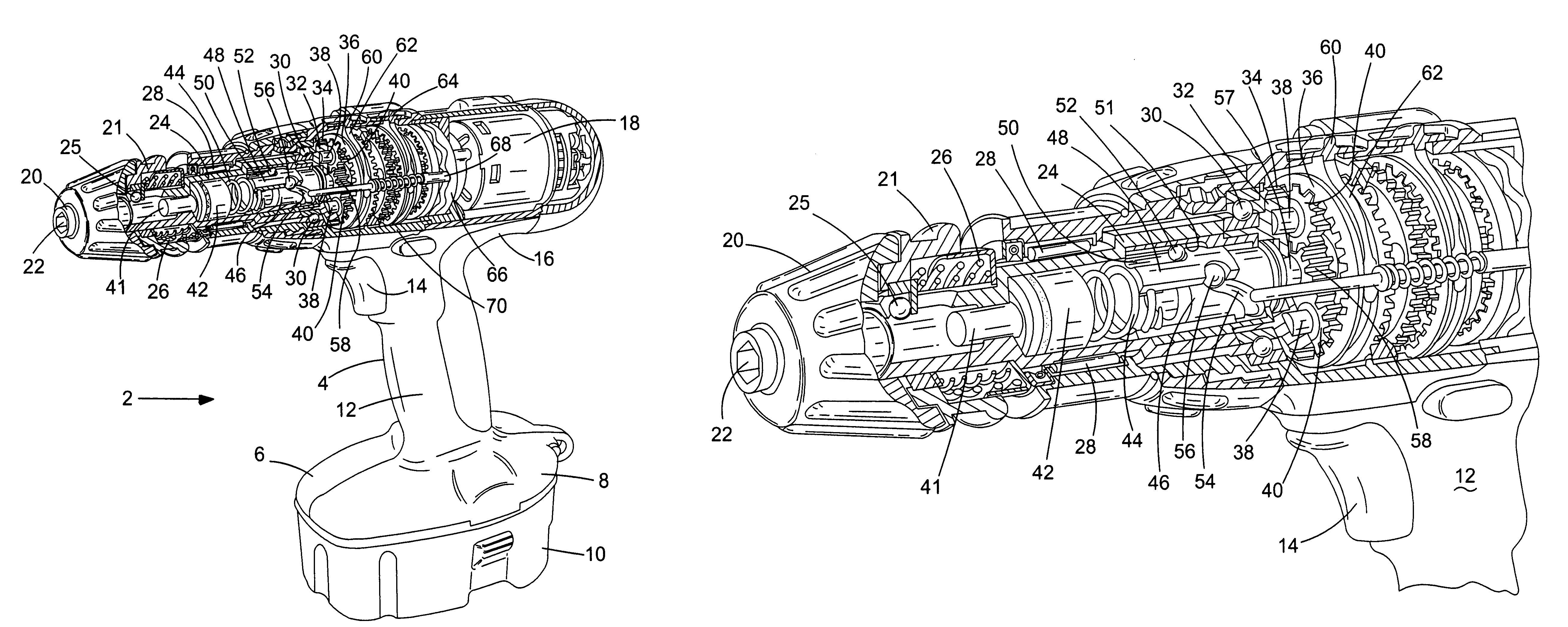
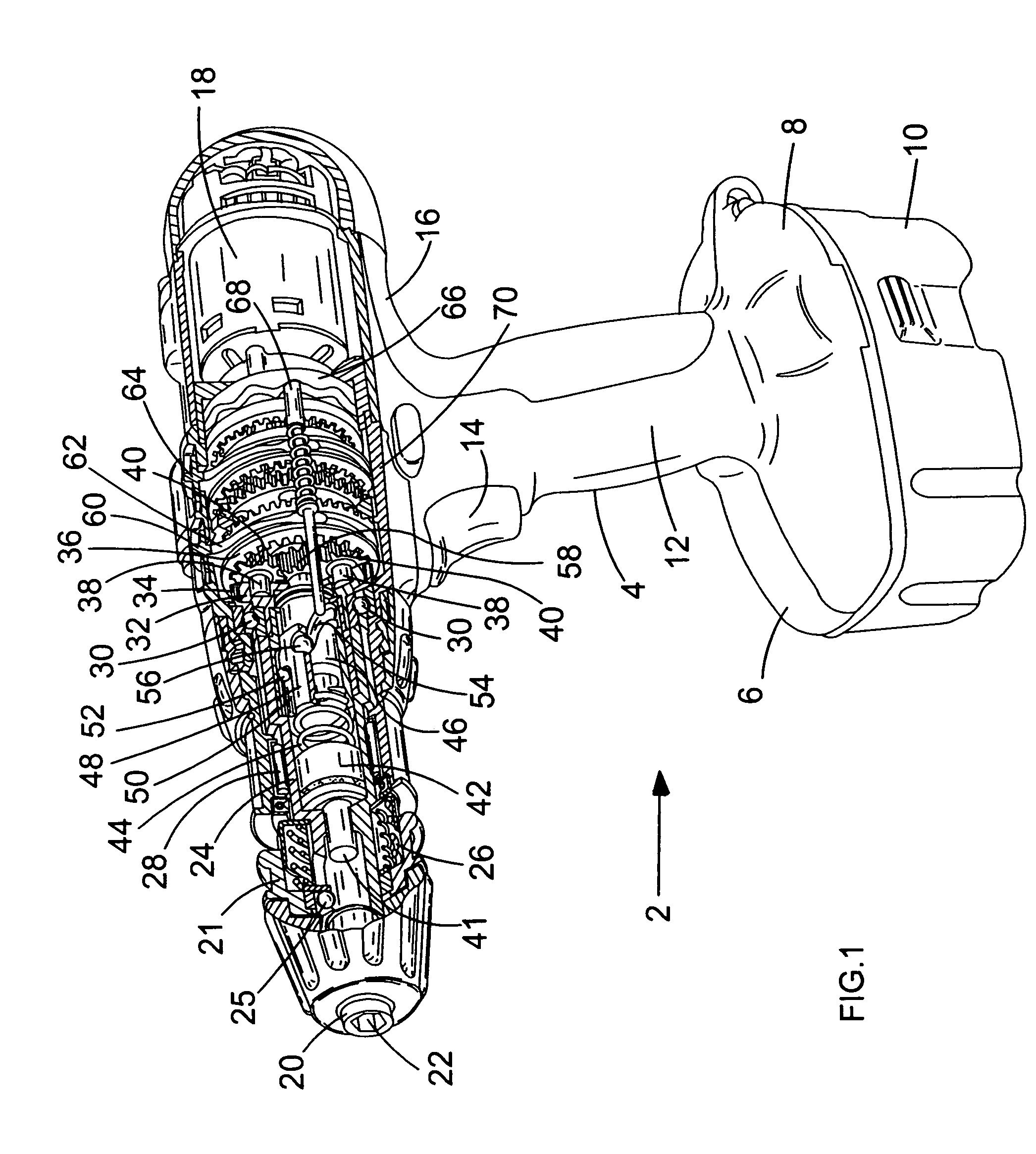
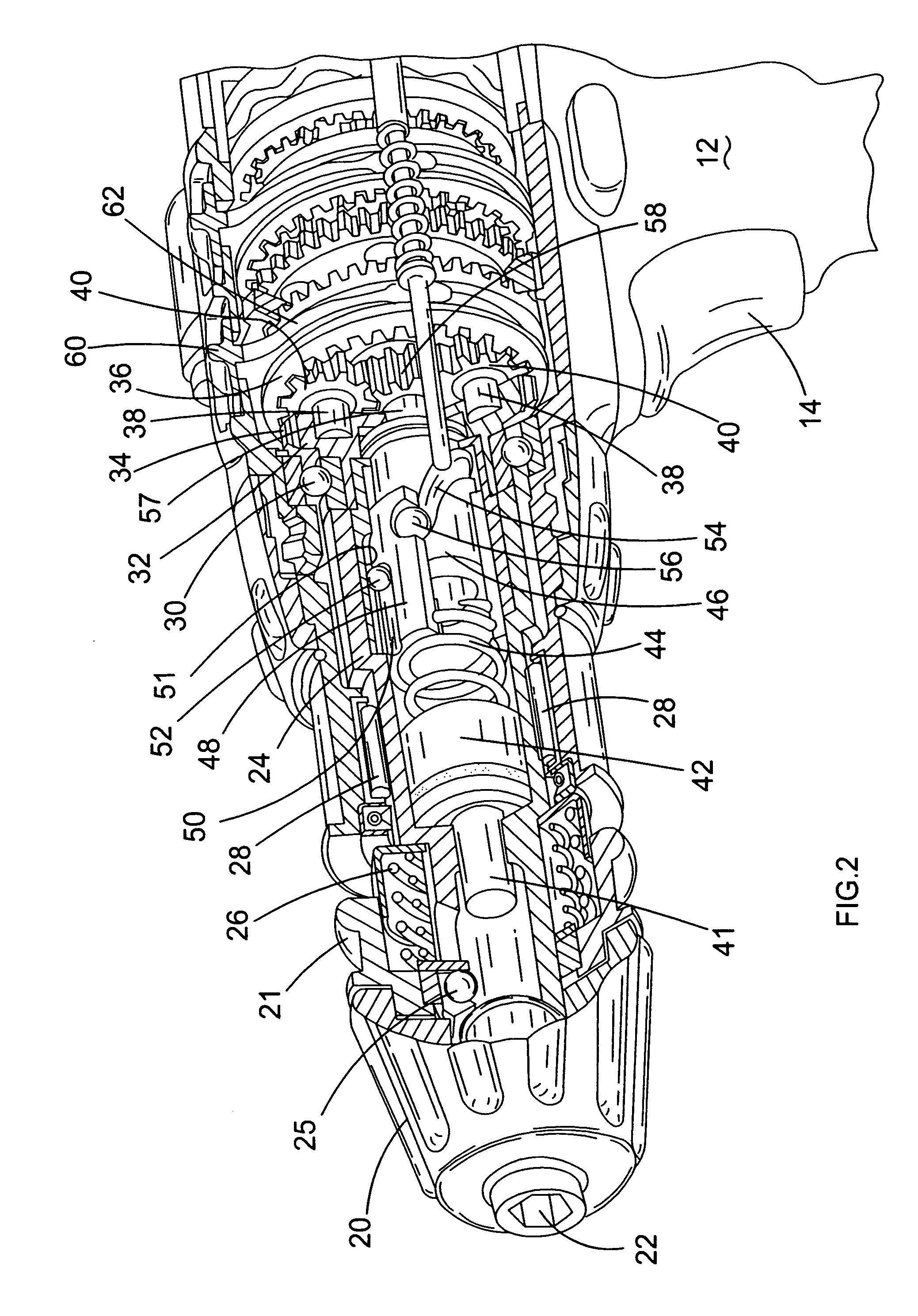
[0025]Referring to FIGS. 1 and 2, a rotary hammer 2 has a housing 4 formed from a pair of mating clam shells 6, 8 of durable plastics material and a removable rechargeable battery 10 removably mounted to a lower part of the housing 4 below a handle 12. The housing 4 defines the handle 12, having a trigger switch 14, and an upper part 16 containing an electric motor 18 actuated by means of trigger switch 14, at a rear part thereof. The electric motor 18 has a rotor which rotates in well known manner when the motor 18 is activated. A chuck 20 is provided at a forward part of the upper part 16 of housing 4 and has an aperture 22 for receiving a drill bit (not shown). The chuck 20 has a gripping ring 21 axially slidably mounted to a hollow spindle 24 for enabling the drill bit to be disengaged from the chuck 20 by rearward displacement of gripping ring 21 relative to the spindle 24 against the action of com...

second embodiment

[0042]The second embodiment will now be described with reference to FIG. 4.

[0043]The second embodiment is similar in design to the first embodiment. Where the same features have been used in the second embodiment as the first, the same reference numbers have been used.

[0044]The difference between the first and second embodiments of the present invention is that the two ball bearings 52,56 in the first embodiment has been replaced by a single ball bearing 100 in the second embodiment. The ball bearing 100 is located within the sinusoidal cam groove 54 of the cam cylinder 46 and the axial groove 51 of the spindle 24 whilst being held within an aperture formed through the wall of the support cylinder 48. The interaction of the ball bearing 100 following the cam groove 54 causes the reciprocating movement of the support cylinder 48. The interaction of the ball bearing 100 following the axial groove 51 causes the rotational movement of the support cylinder 48 with the spindle 24, the axi...

third embodiment

[0045]The third embodiment will now be described with reference to FIG. 5.

[0046]The third embodiment is similar in design to the first embodiment. Where the same features have been used in the third embodiment as the first, the same reference numbers have been used.

[0047]The first difference between the first and third embodiments of the present invention is that the two ball bearings 52,56 in the first embodiment has been replaced by a single ball bearing 200 in the third embodiment (in the same manner as the second embodiment). The ball bearing 200 is located within the sinusoidal cam groove 54 of the cam cylinder 46 and the axial groove 51 of the spindle 24 whilst being held within an aperture formed through the wall of the support cylinder 48. The interaction of the ball bearing 200 following the cam groove 54 causes the reciprocating movement of the support cylinder 48. The interaction of the ball bearing 200 following the axial groove 51 causes the rotational movement of the s...


PUM

PropertyMeasurementUnit
speed of rotationaaaaaaaaaa
speedaaaaaaaaaa
lengthaaaaaaaaaa

Abstract

A reciprocating drive mechanism for a striker in a hammer, a rotary hammer, or a power drill having a hammer action, includes a sinusoidal cam channel formed on a drive member and a cam follower, in the form of a ball bearing, attached to a driven member which, due to the interaction of the cam and cam follower, results in a reciprocating movement of the driven member. Both the drive member and driven member can be rotatingly driven by a motor, their relative speeds resulting in the reciprocating movement of the driven member. The driven member is connected to the striker either via a mechanical helical spring or an air spring.

Description

FIELD OF THE INVENTION[0001]The present invention relates to powered hammers, to powered rotary hammers, and to power drills having a hammer action.BACKGROUND OF THE INVENTION[0002]Rotary hammers are known in which a motor drives a spindle supporting a hammer bit, while at the same time causing a piston tightly fitted within the spindle to execute linear reciprocating motion within the spindle. This motion causes repeated compression of an air cushion between the piston and a ram slidably mounted within the spindle, which causes the ram in turn to execute reciprocating linear motion within the spindle and apply impacts to the hammer bit via a beat piece.[0003]In know designs of rotary hammer, the piston is reciprocatingly driven by the motor via a wobble bearing or crank. However, such designs typical require a large amount of space for such drive systems in relation to the amount of reciprocating movement of the piston.[0004]Further, rotary hammers of this type suffer from the draw...

Claims


Application Information

Patent Timeline
Patent Type & Authority Patents(United States)
IPC IPC(8): B25D15/02B25D11/10B25D16/00
CPCB25D11/104B25D16/006B25D2211/064B25D2211/065B25D2216/0015B25D2216/0023B25D2216/0038B25D2217/0019B25D2217/0023B25D2250/371
Inventor HAHN, NORBERTSTAAS, ERNSTBUCHHOLZ, ACHIMSTIRM, MICHAELBERNHART, RALF
Owner BLACK & DECKER INC
Why Eureka
Try Eureka