Drill Hammer With Three Modes of Operation

a drill hammer and three-mode technology, applied in the field of drill hammer, can solve the problems of increased structural length, increased structural volume and mass, heat development, wear, etc., and achieves the effect of improving the efficiency of the drill hammer, reducing friction losses, and reducing the length of the structur

Active Publication Date: 2008-07-17
ROBERT BOSCH GMBH
View PDF14 Cites 22 Cited by
  • Summary
  • Abstract
  • Description
  • Claims
  • Application Information

AI Technical Summary

Benefits of technology

[0014]Because the shifting hubs embrace the wobble gear wheel and the toothed slaving shaft in a manner fixed against relative rotation and axially displaceably and are displaceable thereon selectively axially to both sides via the adjacent gear wheels, meshing with them in form-locking fashion, so that—in the center position—they are either simultaneously in engagement with the toothed slaving shaft and the wobble gear wheel and the driven gear wheel or, in one of two lateral displacement positions, mesh with either the wobble gear wheel alone or with the driven gear wheel alone, simple changeover of the operating modes of the drill hammer between hammer-drilling, chiseling, and drilling is possible.
[0015]Because the shifting hubs, which in particular comprise sintered metal, have an annular-groovelike slot on their outer circumference, for engagement of a gearshift fork serving as a shifting means, simple shifting means for shifting the gear can be used. Because the gearshift forks—except in shifting operations—engage the slot in the shifting hubs without force, in particular in floating fashion and thus with low friction, the friction losses are low and the efficiency of the drill hammer is improved.
[0016]Because all the teeth of the toothed shaft profile of the wobble gear wheel and of the driven gear wheel, on their side toward the toothed slaving shaft, each have a partial tooth width reduction, in particular of approximately 1 to 2 mm, which leads to a partial widening of the tooth gaps of the toothed shaft profile that serve as synchronizing recesses—easier changeover and entry of the tooth hub teeth of the shifting hubs into the tooth gaps of the toothed shaft profiles is possible.
[0017]Because all the teeth of the shifting hubs, on each of the two face ends, have a partial tooth width reduction of approximately 1 to 2 mm, and the teeth of the toothed shaft profile of the wobble gear wheel and of the driven gear wheel do not have any tooth width reduction, an aid in synchronization is created which is based solely on the design of the shifting sleeve and thus lowers the production cost for the gear.
[0018]Because between the motor and the gear, an intermediate flange is seated, in which one end of the intermediate shaft is rotatably supported, in particular via a needle bearing, the housing, which comprises plastic half-shells, is especially secure against deformation and stable. Because a one-piece shift plate, in particular bent into a U, serves as the shifting means, and one of its legs of the U acts as a gearshift fork and its other leg of the U acts as a locking fork, the shifting mechanism can be produced especially simply.
[0019]Because the locking fork has a tooth profile with which, particularly in the shifting position of the purely reciprocal motion of the gear, can be put into engagement with the tooth profile of the driven shaft and locks the latter in the process, a changeover of the gear to the chiseling mode, or in other words with a purely reciprocating motion of the gear, is possible with a single, simple machine element, and at the same time the driven shaft is locked in a manner fixed against relative rotation.

Problems solved by technology

The sliding gear wheel has the disadvantage that because of the axial lineup of functional elements and sets of teeth, an increased structural length and hence a greater structural volume and mass are necessary for this construction.
In addition, the running gears, meshing with one another, of the sliding gear wheel and hammer barrel gear wheel are under greater stress as a result of the displacement upon changeover of the operating mode than typical running gears, so that their service life is shortened.
Moreover, the shifting hub and / or the sliding gear wheel must always be kept by the shifting means in its shifting positions, counter to the prestressing force of the springs, so that as a result of constant axial bracing of the fixed shifting means on the rotating shifting hub and the sliding gear wheel as well as by axial bracing of the prestressed springs on these parts, increased friction is involved, which leads to corresponding heat development, wear, and a reduction in the efficiency of the gear.

Method used


Image

  • Drill Hammer With Three Modes of Operation
  • Drill Hammer With Three Modes of Operation
  • Drill Hammer With Three Modes of Operation

Examples


Embodiment Construction

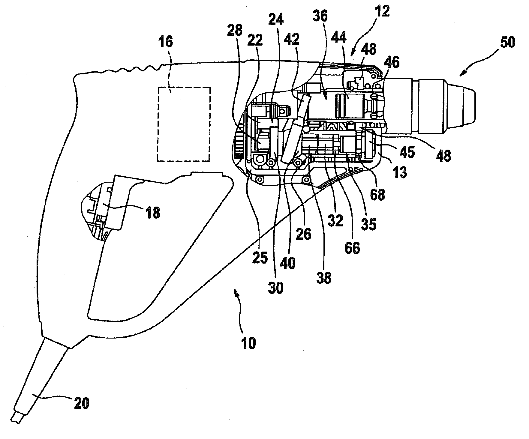
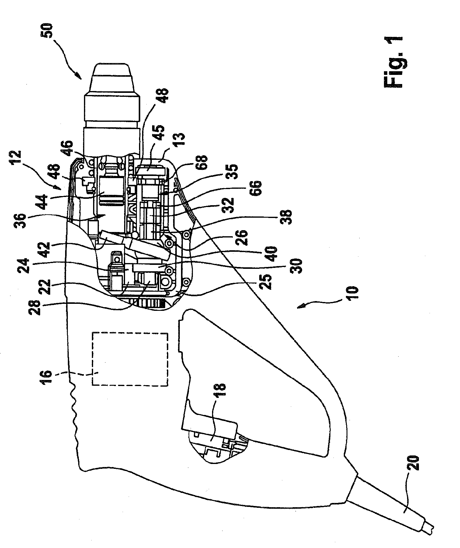
[0035]FIG. 1 shows a drill hammer 10 with a housing 12, which comprises two half-shells 13, 14 of plastic with a vertical parting line, with the upper half-shell 14 removed. The lower half-shell 13 with the functional parts located in it is therefore visible.

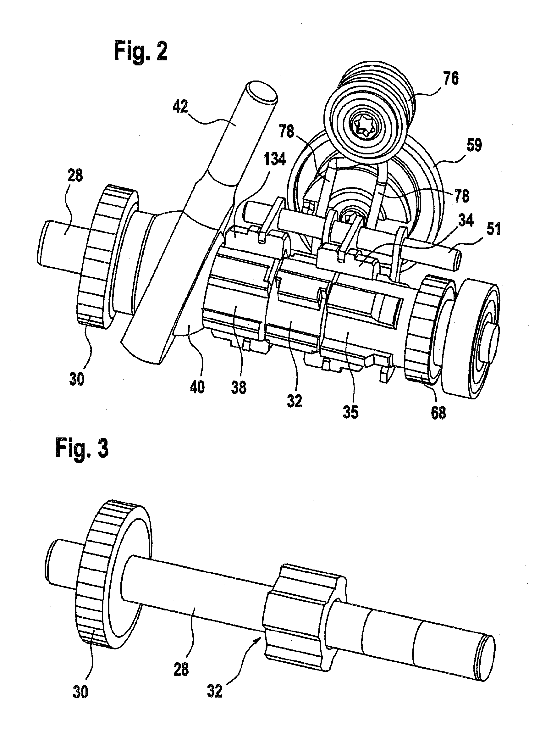
[0036]The housing 12 receives a motor 16 with an on-off switch 18 and a 30 corresponding power cord 20 for connection to an external source of current, as well as a gear 26 and a percussion mechanism 36. The motor 16 includes a motor shaft 22, whose free end has a motor pinion 24 that is supported in an intermediate flange 25 that can be positionally secured between the half-shells 13, 14. The motor pinion 24 is in engagement with a driving gear wheel 30 of an intermediate shaft 28 of the gear 26 that is supported by one end in the intermediate flange 25, via a needle bearing, not shown. Adjoining this, adjacent to the driving gear wheel 30 that is firmly seated on the intermediate shaft, in particular pressed onto it, a wobble ...


PUM

PropertyMeasurementUnit
widthaaaaaaaaaa
lengthaaaaaaaaaa
displacement distanceaaaaaaaaaa

Abstract

A hammer drill (10), consisting of a housing (12), accommodating the parts mentioned below and assembled in particular from half shells (13, 14), a motor (16) with an on/off switch (18) and with a motor shaft (22) with motor pinion (24), a gear unit (26) with an intermediate shaft (28), with a drive gear (30), with a splined driving shaft (32), with a shifting sleeve (34) and with an output gear (35), a percussion mechanism (36), in particular with a wobble plate (40), with a wobble gear (38) with wobble finger (42), and with a percussion element (44), an output shaft (46) with a drive gear (48), and a drill chuck (50), wherein the motor (16) meshes with the drive gear (30) of the intermediate shaft (28) via its motor pinion (24), wherein the rotary driving of the wobble plate (40) with the intermediate shaft (28) can be set or stopped via coupling or release of the shifting sleeve (34), in particular with the splined driving shaft, preferably by displacing with shifting means (52), and wherein the rotary driving of the output shaft (46) with the intermediate shaft (28) can be set or stopped via separate means, in particular independently of the shifting sleeve (34), can be produced cost-effectively and works at a high efficiency by virtue of the fact that a second shifting sleeve (134) serves to set the rotation of the output shaft (46), said shifting sleeve (134) enclosing the splined driving shaft (32) and/or the output gear (35) in a positive-locking and axially displaceable shiftable manner.

Description

PRIOR ART[0001]The present application is based on a drill hammer as generically defined by the preamble to claim 1.[0002]From Japanese Patent Application JP 9-272005, a drill hammer with a changeover mechanism for the three modes of operation of drilling, chiseling, and hammer-drilling is known. The drill hammer has an electric motor, which via a motor pinion meshes with a drive pinion of an intermediate shaft. The drive pinion is seated, in a manner fixed against relative rotation, on the intermediate shaft and transmits the rotary motion of the motor to the intermediate shaft. A toothed slaving shaft is also seated, approximately centrally, on the intermediate shaft in a manner fixed against relative rotation.[0003]A drive bearing for a hammering percussion mechanism is seated, rotatably and rotationally lockably, on the intermediate shaft, axially adjacent to the first side of the toothed slaving shaft. With it, the rotation of the intermediate shaft can be converted into an axi...

Claims


Application Information

Patent Timeline
Patent Type & Authority Applications(United States)
IPC IPC(8): B25D16/00B25D11/00
CPCB25D16/006B25D2211/061B25D2216/0015B25D2250/371B25D2216/0038B25D2216/0046B25D2216/0076B25D2216/0023
Inventor DUESSELBERG, ACHIMULLRICH, ANDREHEINZELMANN, HELMUTBERNHARDT, THOMASWEISS, MICHAELHERR, TOBIAS
Owner ROBERT BOSCH GMBH
Why Eureka
Try Eureka