Hammer drill

a hammer drill and hammer mechanism technology, applied in the field of hammer drills, can solve the problems of operator hands injury, vibration generated by the operation of the hammer mechanism, so as to reduce the amount, reduce the effect of vibration, and reduce the amoun

Active Publication Date: 2011-06-02
BLACK & DECKER INC
View PDF10 Cites 24 Cited by
  • Summary
  • Abstract
  • Description
  • Claims
  • Application Information

AI Technical Summary

Benefits of technology

[0006]A problem associated with hammer drills is the vibration generated by the operation of the hammer drill, and in particular, the vibration generated by the operation of the hammer mechanism. This vibration is transferred to the hands of the operator holding the handles of the hammer drill, particularly through the rear handle. This can result in the injury of the hands of the operator. As such, it is desirable to minimise the effect of vibration experienced by the hands of the operator. This is achieved by reducing the amount by which the handle vibrates.
[0007]There are two ways of reducing the amount by which the rear handle vibrates. The first method is to reduce the amount of vibration produced by the whole hammer drill. The second method is to reduce the amount of vibration transferred from the body of the hammer drill to the rear handle. The present invention relates to the second method.
[0008]EP1529603 discloses a dampening mechanism for a rear handle by which the amount of vibration transferred from the body to the handle is reduced.
[0009]The rear handle is slideably mounted on the body using connectors 230. Springs 220 bias the handle 202 rearwardly away from the housing 212, and which act to dampen vibration to reduce the amount transferred from the housing 212 to the handle 202. A movement co-ordination mechanism is provided, which comprises an axial 216, which interacts with the connectors 230 to ensure that the movement of the two ends of the handle are in unison.

Problems solved by technology

A problem associated with hammer drills is the vibration generated by the operation of the hammer drill, and in particular, the vibration generated by the operation of the hammer mechanism.
This can result in the injury of the hands of the operator.

Method used


Image

  • Hammer drill
  • Hammer drill
  • Hammer drill

Examples


first embodiment

[0058]the present invention will now be described with reference to FIGS. 1 to 6.

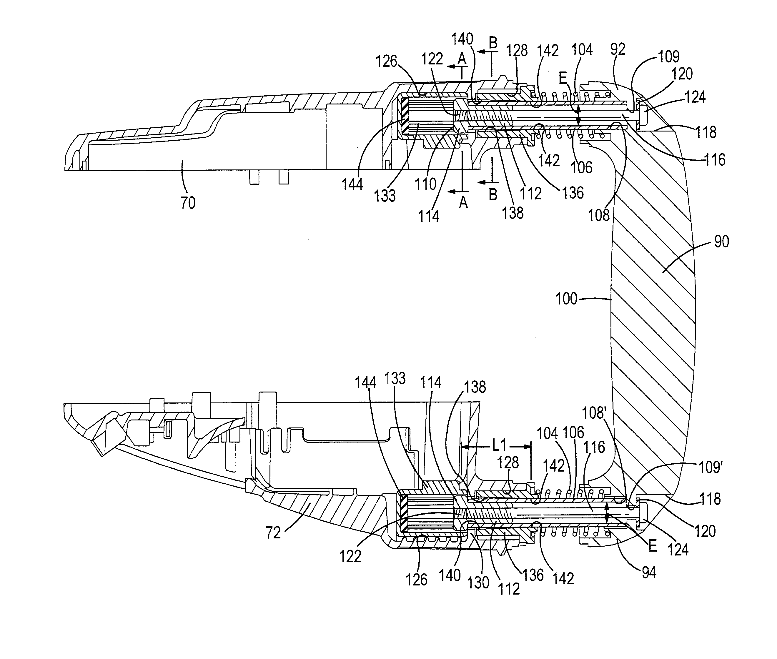
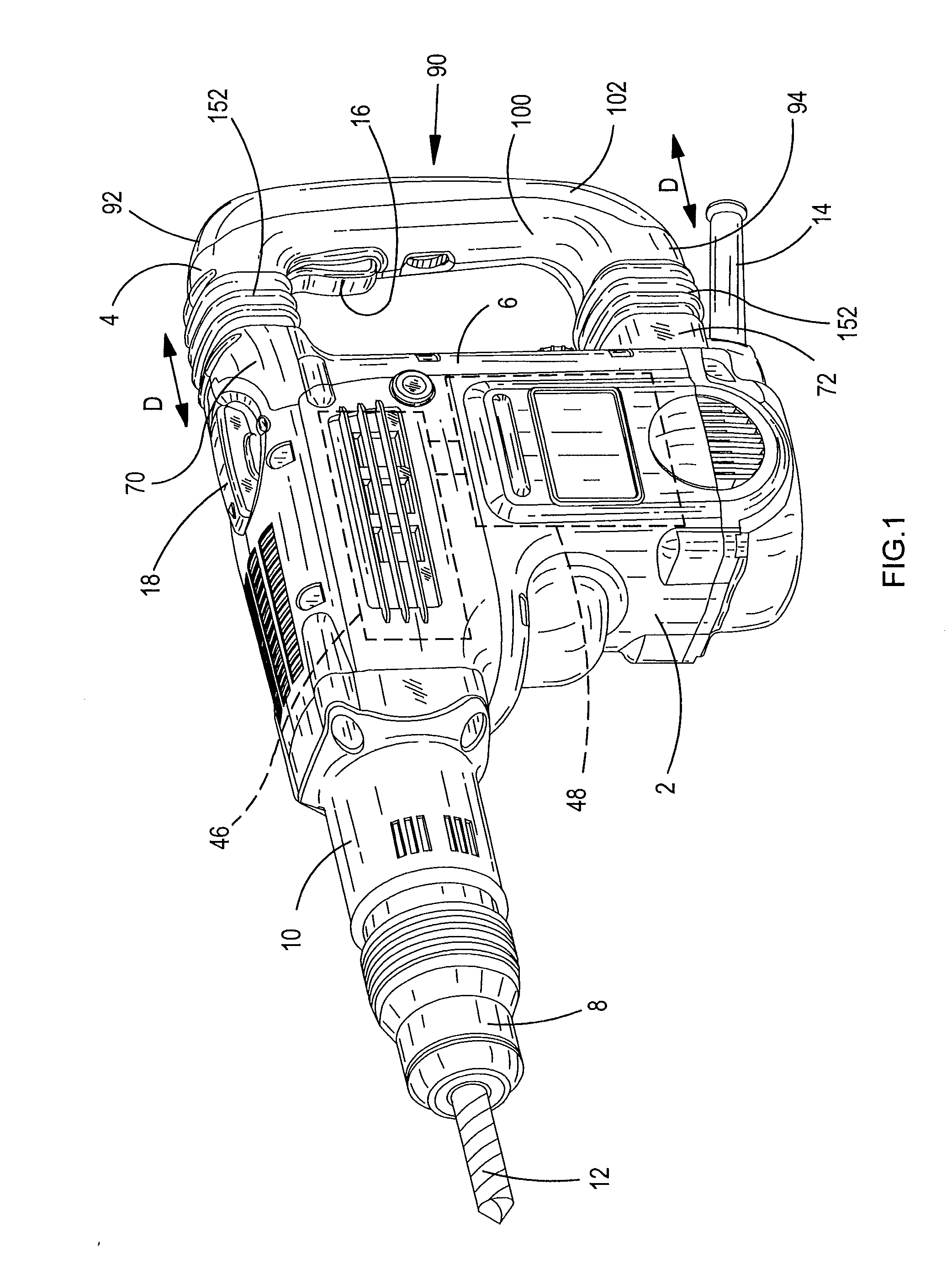
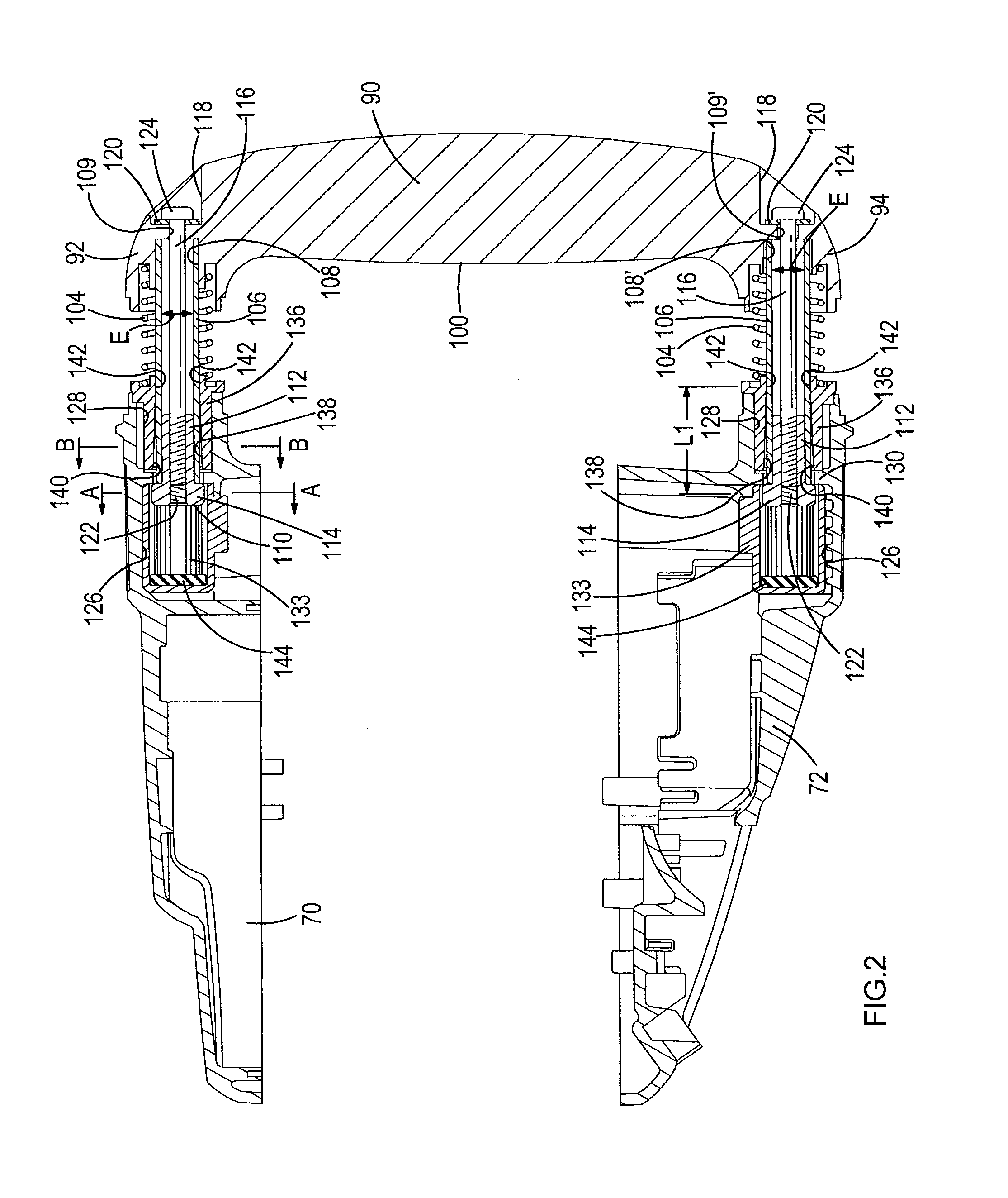
[0059]Referring to FIG. 1, the hammer drill comprises a body 2 having a rear handle 4 moveably mounted to the rear of the body 2. The rear handle 4 comprises a centre grip section 90 and two end connection sections 92; 94, one end connection section being attached to one end of the centre grip section, the other end connection section being connected to the other end of the centre grip section. The handle 4 is connected to the rear of the body 2 by the two end connection sections 92, 94. The rear handle is constructed from a plastic clam shell 100 and a rear end cap 102 which is attached to the clam shell 100 using screws (not shown). The rear of the body is formed by three plastic clam shells 6, 70, 72 which attach to each other and to the remainder of the body 2 using screws (not shown).

[0060]A tool holder 8 is mounted onto the front 10 of the body 2. The tool holder can hold a cutting tool 12, such a...


PUM

PropertyMeasurementUnit
lengthaaaaaaaaaa
shapeaaaaaaaaaa
dimensionsaaaaaaaaaa

Abstract

A hammer drill comprising: a body 2 in which is mounted a motor 48 and a hammer mechanism 46 which is driven by the motor 48 when the motor 48 is activated; a tool holder 8 mounted on the front of the body 2 and which is capable of holding a cutting tool 12, the hammer mechanism 46, when driven by the motor 48, capable of imparting impacts to the cutting tool 12, when held by the tool holder 8; a rear handle 4, moveably mounted on to the rear of the body 2 via at least one movement control mechanism and which is capable of moving towards or away from the body 2; a biasing mechanism 104 which biases the rear handle 4 away from the body 2; wherein each movement control mechanism comprises: a first mount; a rod 106, having a longitudinal axis 107, rigidly connected at one of it ends to the first mount; a second mount which slidingly engages with the rod 106 at two distinct points only along its length to allow the rod 106 to slide relative to the second mount in a direction parallel to the longitudinal axis 107 whilst preventing the rod 106 from moving relative to second mount in a direction perpendicular to longitudinal axis 107; wherein one mount 70, 133, 136 is attached to the body 2 and the other mount 92 is attached to the rear handle 4.

Description

FIELD OF THE INVENTION[0001]The present invention relates to a hammer drill, and in particular, a vibration dampening mechanism for a handle of a hammer drill.BACKGROUND OF THE INVENTION[0002]A typical hammer drill comprises a body in which is mounted an electric motor and a hammer mechanism. A tool holder is mounted on the front of the body which holds a cutting tool, such as a drill bit or a chisel. The hammer mechanism typically comprises a slideable ram reciprocatingly driven by a piston, the piston being reciprocatingly driven by the motor via a set of gears and a crank mechanism or wobble bearing. The ram repeatedly strikes the end of the cutting tool via a beat piece. When the only action on the tool bit is the repetitive striking of its end by the beat piece, the hammer drill is operating in a hammer only mode.[0003]Certain types of hammer drill also comprise a rotary drive mechanism which enables the tool holder to rotatingly drive the cutting tool held within the tool hold...

Claims


Application Information

Patent Timeline
Patent Type & Authority Applications(United States)
IPC IPC(8): B25D17/24
CPCY10T16/48B25D17/043B25D2250/371
Inventor FRIEDRICH, ANDREASBERGHAUSER, ULRICHHARCAR, FRANTISEK
Owner BLACK & DECKER INC
Why Eureka
Try Eureka