Well casing installation and removal apparatus and method

a well casing and adapter technology, applied in the direction of manufacturing tools, sealing/packing, borehole/well accessories, etc., can solve the problem that the aforedescribed hammer drill cannot be used to apply upwardly directed hammering

Inactive Publication Date: 2003-07-08
ALLYN JOHN F +1
View PDF9 Cites 23 Cited by
  • Summary
  • Abstract
  • Description
  • Claims
  • Application Information

AI Technical Summary

Problems solved by technology

However, a hammer drill arranged in the aforedescribed manner cannot be employed to apply upwardly directed hammering force to a well casing to remove the casing from the ground because upward movement of the hammer drill renders the tool inoperative.

Method used


Image

  • Well casing installation and removal apparatus and method
  • Well casing installation and removal apparatus and method
  • Well casing installation and removal apparatus and method

Examples


Embodiment Construction

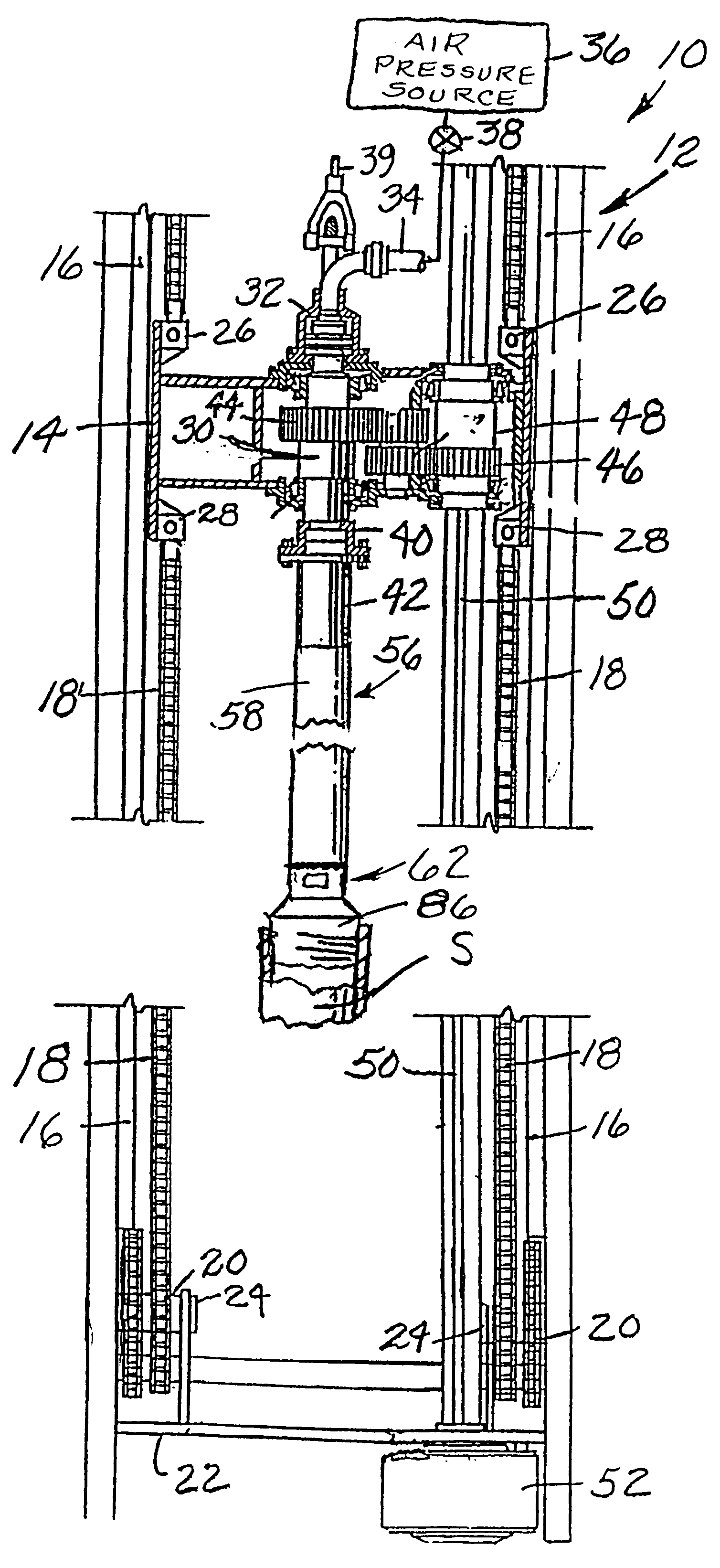
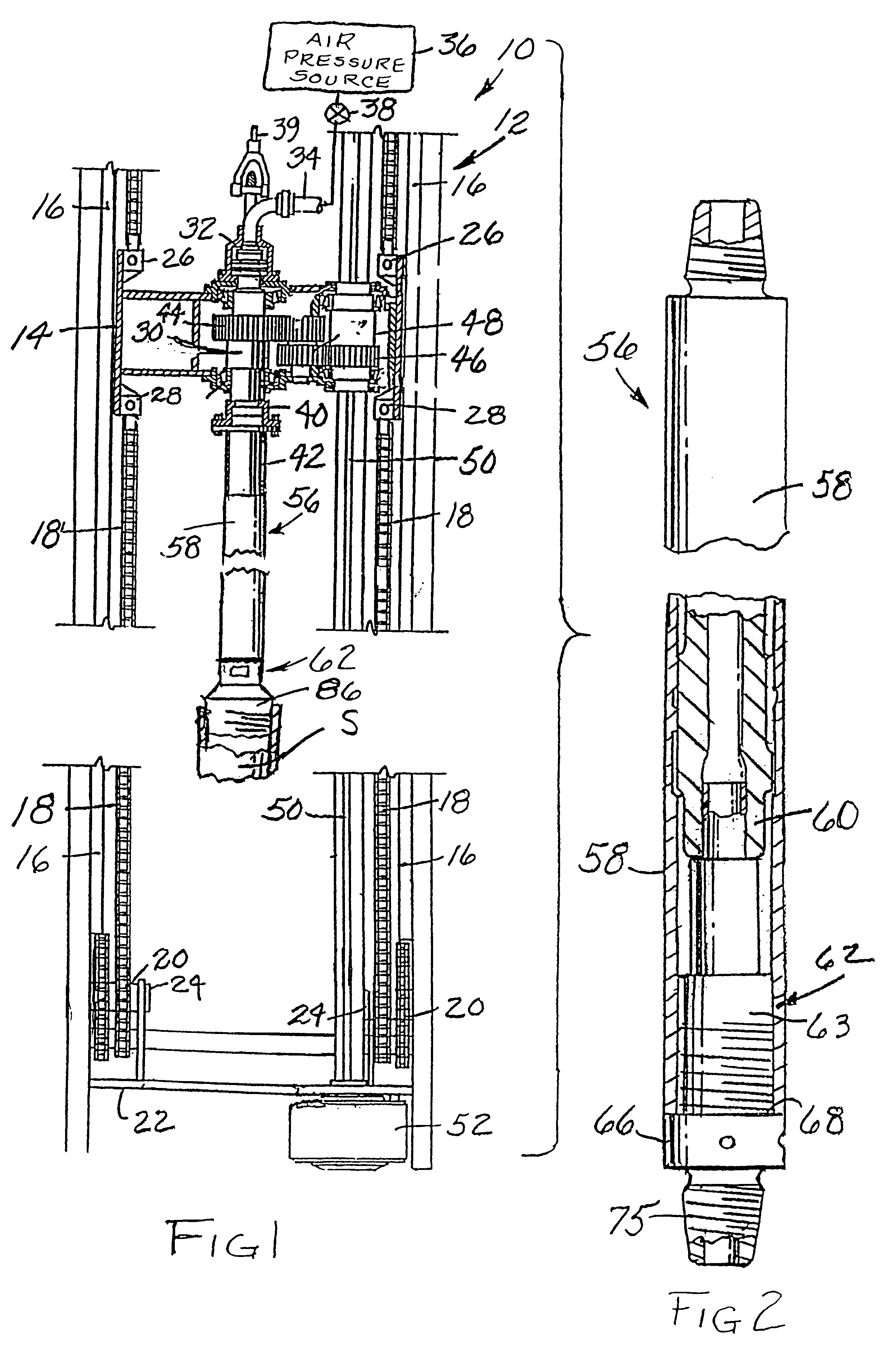
The present invention is concerned with improvements in a well drilling machine of the type having an above-ground mast or tower with a topdrive rotary head or rotary-table drive capable of sinking a well casing and feeding and retracting a downhole drill and a method for utilizing such apparatus to install or remove well casing or the like.

In the drawings and in the description which follows the invention is illustrated and described with reference to an above-ground portion of a drilling machine of the aforedescribed type indicated generally by the numeral 10. The illustrated apparatus 10, shown in FIG. 1, includes a mast or tower indicated generally at 12 and having a traveling head or transmission 14 slideably guided for up and down travel along horizontally opposed and vertically extending guide ways 16, 16 mounted at opposite sides of the mast 12. The traveling head 14 is raised and lowered on the guides by chains 18, 18 which comprise part of a hoisting mechanism and operate ...


PUM


Abstract

A downhole well drilling apparatus includes an above-ground mast and an axially elongated generally cylindrical pneumatic hammer drill supported by the mast and mounted in an axially vertical above-ground position. An installation and removal adapter mounted on the lower end of the pneumatic hammer drill couples the hammer drill to a pipe string and maintains a movable part of the hammer drill in an operative condition at all times thereby enabling the hammer drill to operate while rotational torque and upward directed force are simultaneously applied to the operating hammer drill by the apparatus during removal of a casing from a downhole position. Hammer operation is controlled by a manually operable air supply valve.

Description

This invention relates in general to downhole drilling apparatus and deals more particularly with an improved apparatus and method for installing well casing or removing well casing or a drill rod which may be stuck in a bore hole.A downhole drilling apparatus of the type with which the present invention is concerned utilizes an air hammer drill mounted at the downhole end of a pipe string to drive a drill bit. The hammer drill includes an axially elongated cylindrical hammer casing or barrel which is mounted on and depends from the lower end of the pipe string. A hammer chuck threadably connected in fixed position to the lower end of the hammer barrel carries an axially vertically reciprocally moveable drill bit having an upwardly facing bit shoulder disposed in opposing relation to a downwardly facing arresting surface on the lower end of the drill chuck. The bit shoulder is normally spaced a substantial distance below the arresting surface, as for example, 2 to 3 inches below the...

Claims


Application Information

Patent Timeline
Patent Type & Authority Patents(United States)
IPC IPC(8): E21B31/00E21B17/02E21B7/20E21B17/03E21B31/107E21B4/14E21B4/00E21B4/20
CPCE21B4/14E21B4/20E21B7/208E21B17/03E21B31/107
Inventor ALLYN, JOHN F.ALLYN, WALTER G.
Owner ALLYN JOHN F
Why Eureka
Try Eureka