Underground well electrical cable transition with seals and drain

a technology of underground wells and electrical cables, applied in the direction of cable terminations, cable casings/cabinets/drawers, electrical apparatus casings/cabinets/drawers, etc., can solve the problems of large number of parts and require a substantial amount of time to compl

Inactive Publication Date: 2001-03-20
MOORE BOYD B
View PDF28 Cites 54 Cited by
  • Summary
  • Abstract
  • Description
  • Claims
  • Application Information

AI Technical Summary

Problems solved by technology

While these types of penetrators have proven to be safe and effective, they require a relatively large number of parts and, since the splice between the el...

Method used


Image

  • Underground well electrical cable transition with seals and drain
  • Underground well electrical cable transition with seals and drain
  • Underground well electrical cable transition with seals and drain

Examples


Embodiment Construction

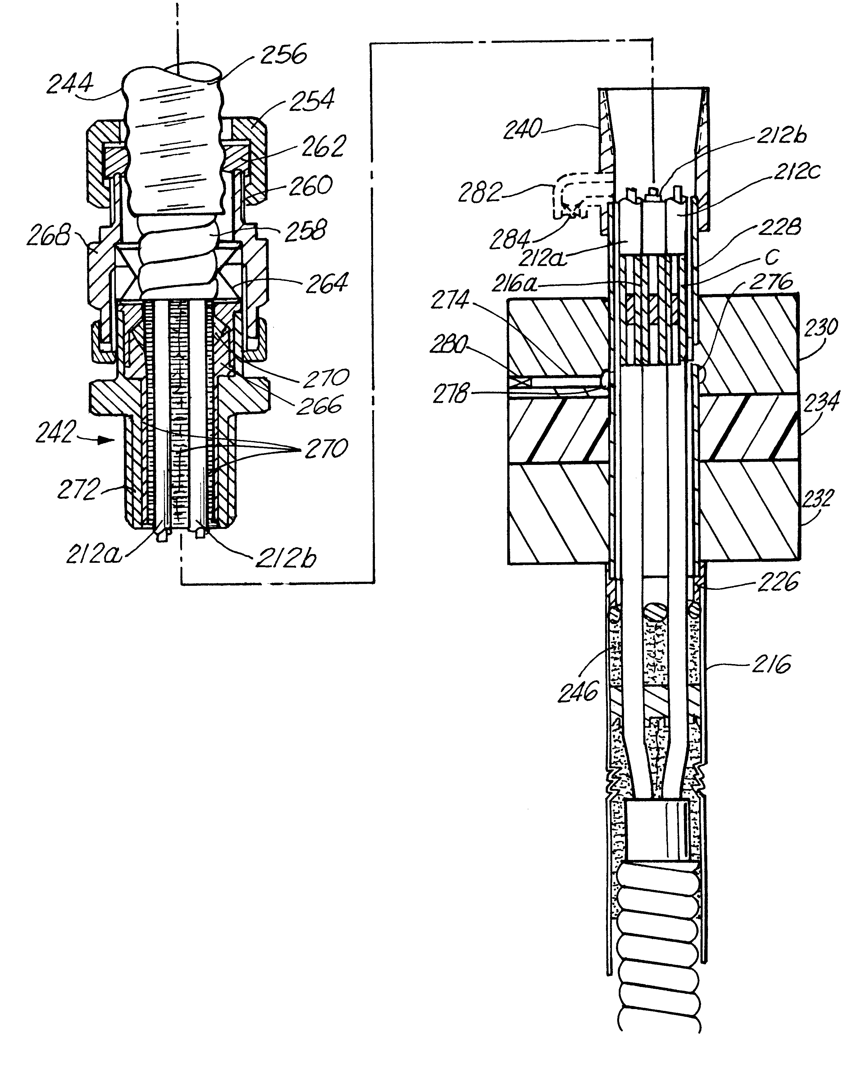
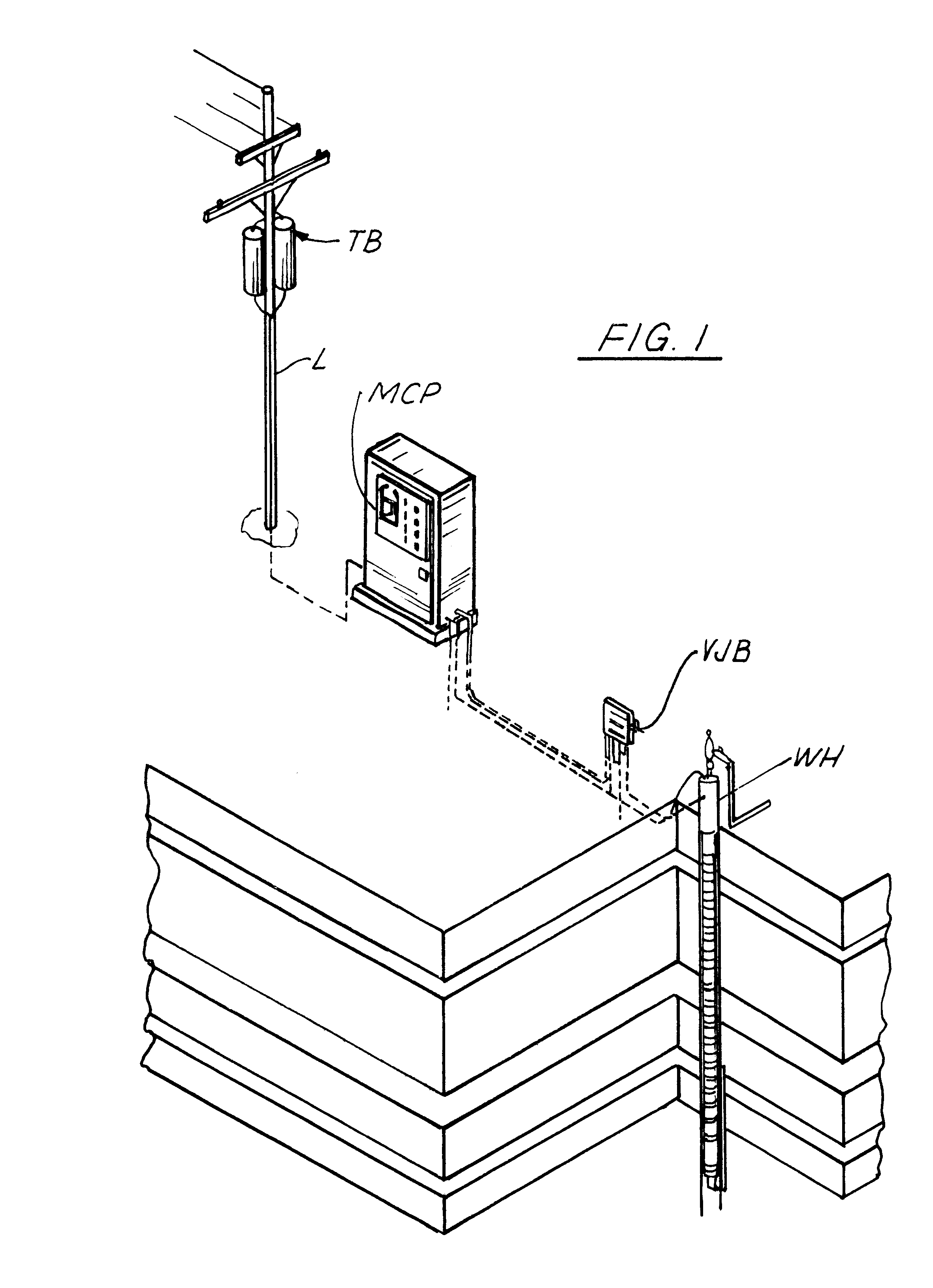
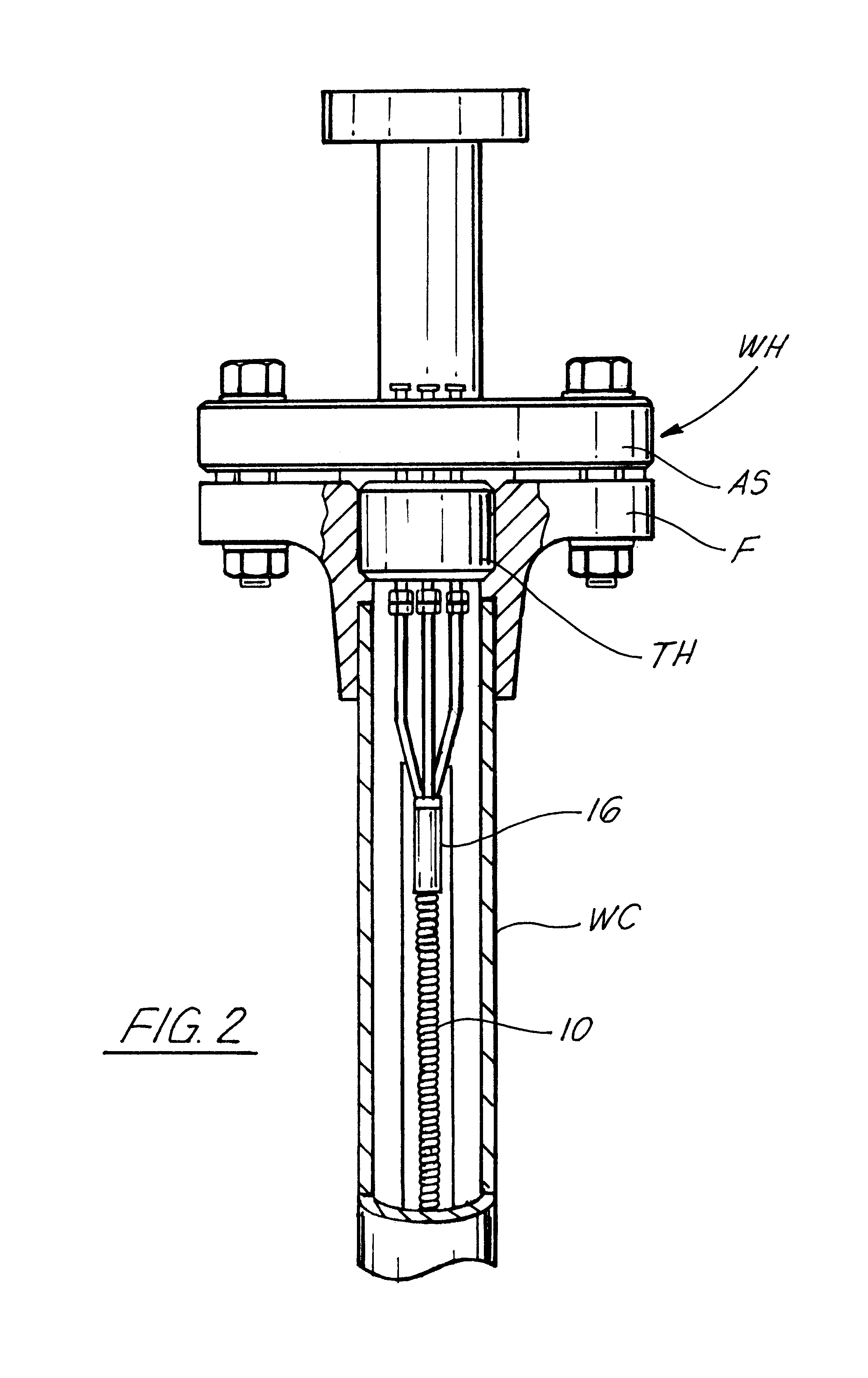
The subject invention relates to a penetrator for electrical conductor cable which transmits electrical power from an above-ground remote electrical power source (not shown) to downhole electrical equipment such as submersible pumps. Penetrators which have previously been sold, such as the one shown and described in U.S. Pat. No. 5,289,882 and PCT application WO 94 / 25726, involve the formation of a splice in or below the wellhead barrier, between the conductor cable connected to the downhole equipment and the conductor cable connected to the remote power source.

The invention described in detail in U.S. patent application Ser. No. 08 / 633,244, filed Apr. 16, 1996, was directed to a different type of transition or penetrator for electrical conductor cable which eliminated the splice between the cable connected to the downhole equipment and the power source conductor cable. In other words, any break or interruption in the electrical cable from the downhole equipment was eliminated as it...


PUM


Abstract

A transition for electrical well cable through the wellhead barrier of an underground well leads to an electrical power cable connected to an above-ground electrical power source, where the only connection between the electrical well cable and the electrical power cable is formed inside the wellhead barrier, between approved primary and secondary seals. A drain or vent to the atmosphere is also located between the seals.

Description

1. Field of the InventionThe present invention relates to an improved electrical cable transition and method for an underground well and, more particularly, to a simplified, low cost, transition and method for such a cable. The transition includes NRTL approved primary and secondary seals and a cable connection between the seals along with a drain or vent for venting combustible or flammable well fluids to the atmosphere in case the primary seal leaks.2. Description of the Related ArtIn underground wells such as oil wells, electrical power is furnished to submersible pumps and other downhole equipment through insulated electrical conductors that extend through conduit in the well casing. In order to connect the downhole equipment to a power source outside the well, these conductors must penetrate a wellhead barrier that is sealed to a top opening of the casing. The configuration of cables and seals in the wellhead is called a "penetrator," the purpose for which is to provide a trans...

Claims


Application Information

Patent Timeline
IPC IPC(8): E21B17/00E21B33/03E21B33/04H02G15/06H02G15/04H02G15/02
CPCE21B17/003E21B33/0407H02G15/04H02G15/06
Inventor MOORE, BOYD B.
Owner MOORE BOYD B
Why Eureka
Try Eureka