Semiconductor memory device and method for arranging and manufacturing the same
a memory device and semiconductor technology, applied in semiconductor devices, digital storage, instruments, etc., can solve the problems of large chip size and increased area siz
- Summary
- Abstract
- Description
- Claims
- Application Information
AI Technical Summary
Problems solved by technology
Method used
Image
Examples
first embodiment
[0079]FIGS. 7A to 7D are views respectively illustrating arrangement of transistors of a static memory cell and transistors which constitute an inverter, a NAND gate and a NOR gate of a peripheral circuit of a semiconductor memory device according to the present invention. In particular, FIGS. 7A to 7D show arrangement of transistors which constitute the peripheral circuit in case where transistors which constitute the memory cell are arranged on two layers.
[0080]Like arrangement of FIG. 5A, transistors PD1, PD2, PU1, PU2, T1, and T2 of FIG. 7A that constitute the static memory cell are arranged on two layers. As shown in FIG. 7B, an NMOS transistors N1 is arranged on the first layer 1F, and a PMOS transistor P1 is arranged on the second layer 2F. Connection between the transistors N1 and P1, which constitute the inverter, are identical to those of FIG. 4B. As shown in FIG. 7C, NMOS transistors N2 and N3 are arranged on the first layer 1F, and PMOS transistors P2 and P3 are arranged...
second embodiment
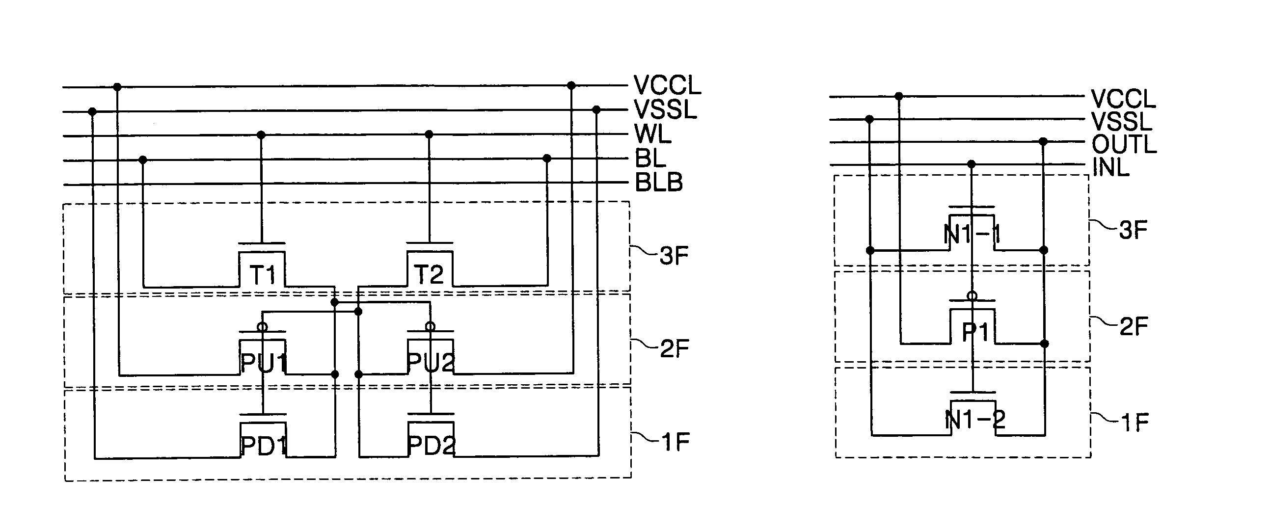
[0082]FIGS. 8A to 8D are views respectively illustrating arrangement of transistors of a static memory cell and transistors which constitute an inverter, a NAND gate and a NOR gate of a peripheral circuit of a semiconductor memory device according to the present invention. In particular, FIGS. 8A to 8D show arrangement of transistors which constitute the peripheral circuit in case where transistors which constitute the memory cell are arranged on three layers. Like arrangement of FIG. 6A, the transistors of FIG. 8A, which constitute the static memory cell, are arranged such that the pull-down transistors PD1 and PD2 are arranged on the first layer 1F, the pull-up transistors PU1 and PU2 are arranged on the second layer 2F, and the transmission transistors T1 and T2 are arranged on the third layer. As shown in FIG. 8B, NMOS transistors N1-1 and N1-2, which have ½ channel width of channel width of the NMOS transistor N1 of FIG. 3B are arranged. The NMOS transistor N1-2 is arranged on ...
third embodiment
[0086]FIGS. 9A to 9D are views respectively illustrating the arrangement of transistors of a static memory cell and transistors which constitute an inverter, a NAND gate and a NOR gate of a peripheral circuit of a semiconductor memory device according to the present invention. In particular, FIGS. 9A to 9D show arrangement of transistors which constitute the peripheral circuit in case where transistors which constitute the memory cell are arranged on three layers. Like the arrangement of FIG. 8A, the transistors of FIG. 9A, which constitute the static memory cell, are arranged on three layers.
[0087]As shown in FIG. 9B, PMOS transistors P1-1 and P1-2 which have ½ channel width of channel width of the PMOS transistor P1 which constitutes the inverter are arranged. The PMOS transistor P1-1 is arranged on the first layer 1F, the PMOS transistor P1-2 is arranged on the second layer 2F, and the NMOS transistor N1 is arranged on the third layer 3F. Gates, drains and sources of the PMOS tra...
PUM
 Abstract
Description
Claims
Application Information
 - R&D
- Intellectual Property
- Life Sciences
- Materials
- Tech Scout
- Unparalleled Data Quality
- Higher Quality Content
- 60% Fewer Hallucinations
Browse by: Latest US Patents, China's latest patents, Technical Efficacy Thesaurus, Application Domain, Technology Topic, Popular Technical Reports.
© 2025 PatSnap. All rights reserved.Legal|Privacy policy|Modern Slavery Act Transparency Statement|Sitemap|About US| Contact US: help@patsnap.com


