Cochlear implant electrode and method of making same

a cochlea implant and electrode technology, applied in the field of implantable stimulation devices, can solve the problems of coil wires not being compactly bundled, more susceptible to bending fractures, etc., and achieve the effects of preventing super-flexibility, facilitating conformation to curvature, and increasing stiffness

Inactive Publication Date: 2008-01-01
ADVANCED BIONICS AG
View PDF36 Cites 36 Cited by
  • Summary
  • Abstract
  • Description
  • Claims
  • Application Information

AI Technical Summary

Benefits of technology

[0020]Use of a Teflon tubing in the lead serves two major purposes. First, the Teflon is much stiffer than carrier material which is generally silicone or polyurethane. Incorporating a Teflon tubing therefore provides added stiffness to that part of the lead. Second, the Teflon tubing makes inserting and withdrawing a stylet into and out of the stylet insertion channel much easier because Teflon is a harder material and exhibits less friction than silicone or polyurethane. As a consequence, Teflon also does not tear as easily as the carrier material.
[0021]As yet another embodiment of the lead of the present invention, an overmold can be attached over the opening of the stylet insertion channel to minimize fluid and bacteria from entering the stylet insertion channel. The overmold may be made from the same material as the lead carrier material, e.g., silicone or polyurethane. A slit in the overmold is placed to allow passage of the insertion stylet through the slit and into the stylet insertion channel. The slit must be sized and configured to permit the stylet to pass easily through the slit. After the stylet is withdrawn, the slit, being made of a compliant material, will self-seal to some extent, as it returns to its original conformation.
[0024]Another, second embodiment of the cochlear lead is suited for deep, lateral (outer) wall placement in the scala tympani. With this embodiment, the distal section of the lead is hooked shape. This hooked, curved portion is comparatively longer than the lead embodiment for medial placement, in order to allow the second lead embodiment to be implanted into the scala tympani between about 1 to 2 turns. Because of the hook shape, when the second embodiment of the lead is implanted, the lateral side of the lead contacts the lateral or outer wall of the scala tympani. Such lateral contact may facilitate the deeper, up to 2 turn, implantation of the electrode array.
[0025]As an additional feature of the second cochlear lead embodiment, the very tip of the tapered, curved hook may be constructed to be “super-flexible.” The super-flexible tip is short enough such that only a subset of the electrode contacts are actually part of this super-flexible tip. The super-flexible tip is achieved by (a) making the thickness of the tip very thin relative to the other part of the curved hook and (b) by excluding any part of the stylet insertion channel within this tip, since including a channel would necessarily require too thick a carrier and prevent super-flexibility. The super-flexible tip permits the lead to easily conform to the curvature of the scala tympani as the lead tip is being inserted and also to apply light pressure to the lateral wall of the scala tympani in order to minimize injury to the wall during insertion of the electrode array.
[0030]The presence of the Teflon tubing is advantageous as it presents less friction and is more resistant to tears than the carrier material which is often silicone or polyurethane. An insertion stylet can be more easily inserted into and withdrawn from the Teflon tubing with the reduced possibility of a wall tear in the channel. A second important benefit provided by the Teflon tubing is that it provides differential stiffness to the lead. The distal, tapered, curved portion of the lead can be compliant and gentle while being inserted into the scala tympani, while the substantially straight section of the lead is made stiffer by the presence of the Teflon and thereby facilitates the directional placement of the lead near the target cochlea.

Problems solved by technology

While straight wires can be compactly bundled, they are more susceptible to bending fractures than zigzag or coiled wires.
Coil wires are not as easily bundled compactly as straight or zigzag conductor wires.

Method used


Image

  • Cochlear implant electrode and method of making same
  • Cochlear implant electrode and method of making same
  • Cochlear implant electrode and method of making same

Examples


Embodiment Construction

[0061]The following description is of the best mode presently contemplated for carrying out the invention. This description is not to be taken in a limiting sense, but is made merely for the purpose of describing the general principles of the invention. The scope of the invention should be determined with reference to the claims.

[0062]The cochlear electrode of the present invention may be used with an implantable multi-channel pulse generator, e.g., an implantable cochlear stimulator (ICS) of the type disclosed in U.S. Pat. No. 5,603,726, incorporated herein by reference in its entirety or with other suitable stimulators. It is to be understood, however, that although a cochlear lead is used as an exemplary context, the lead of the present invention, including the method of manufacturing, may be applied to other medical applications.

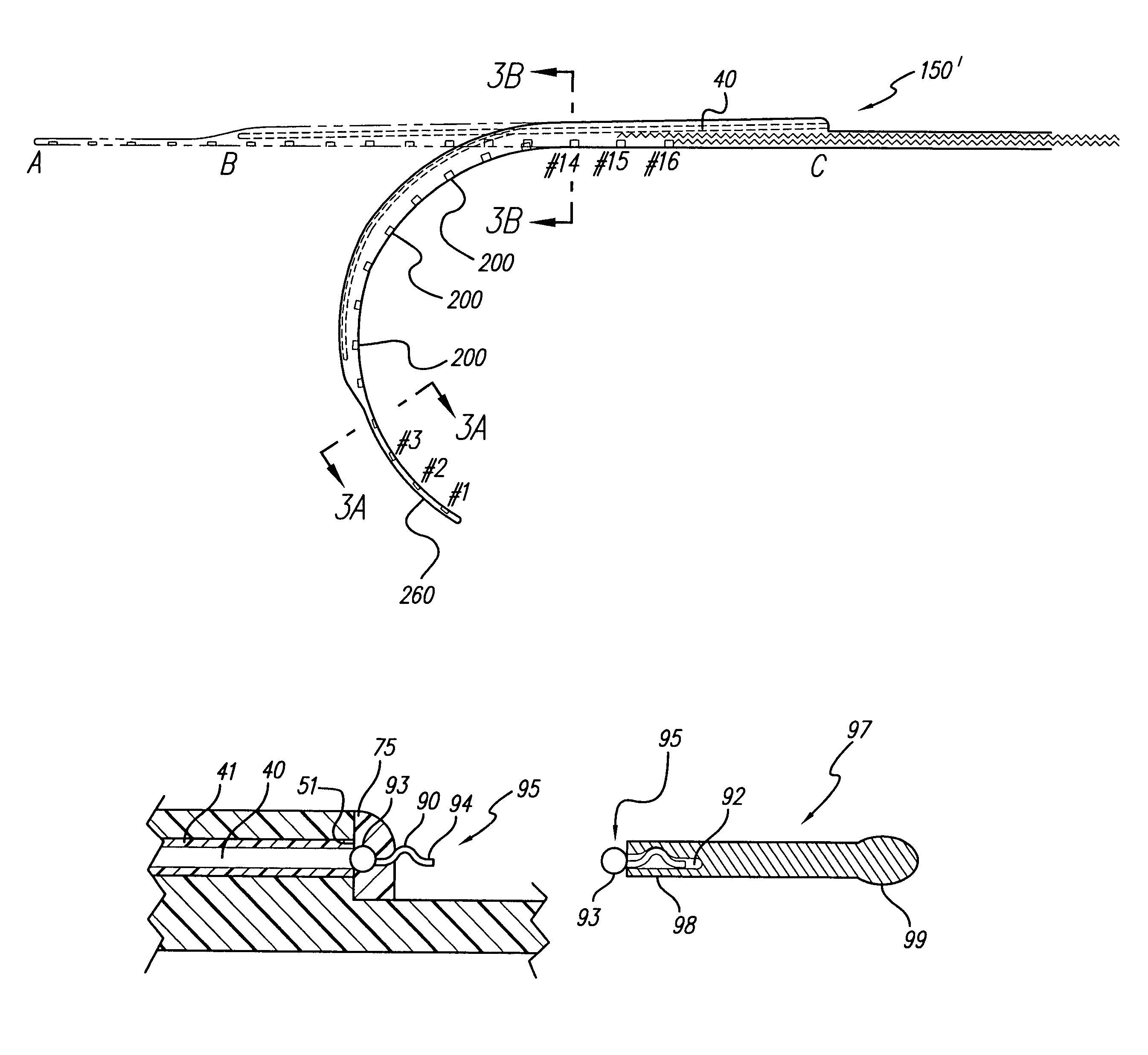
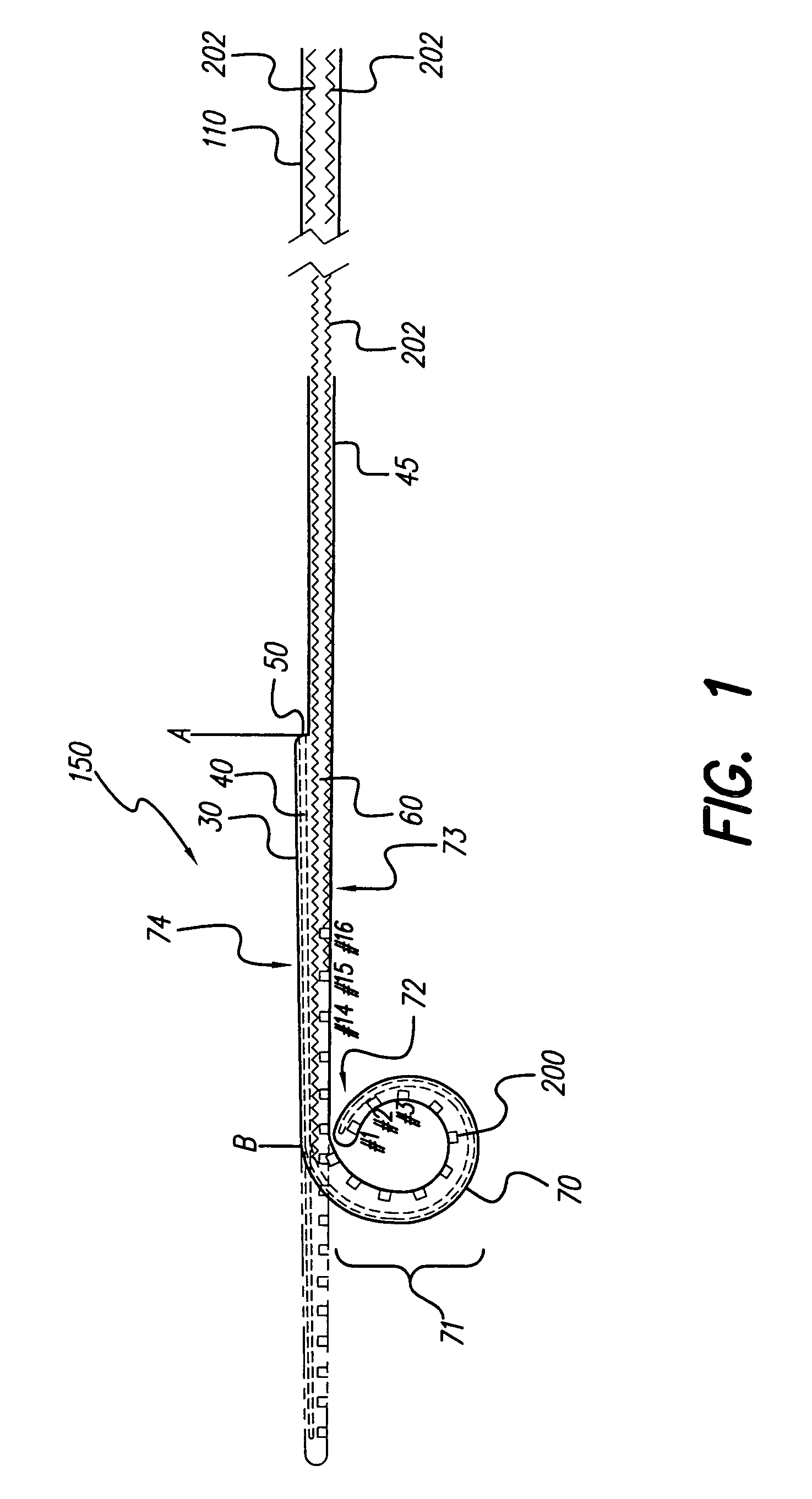
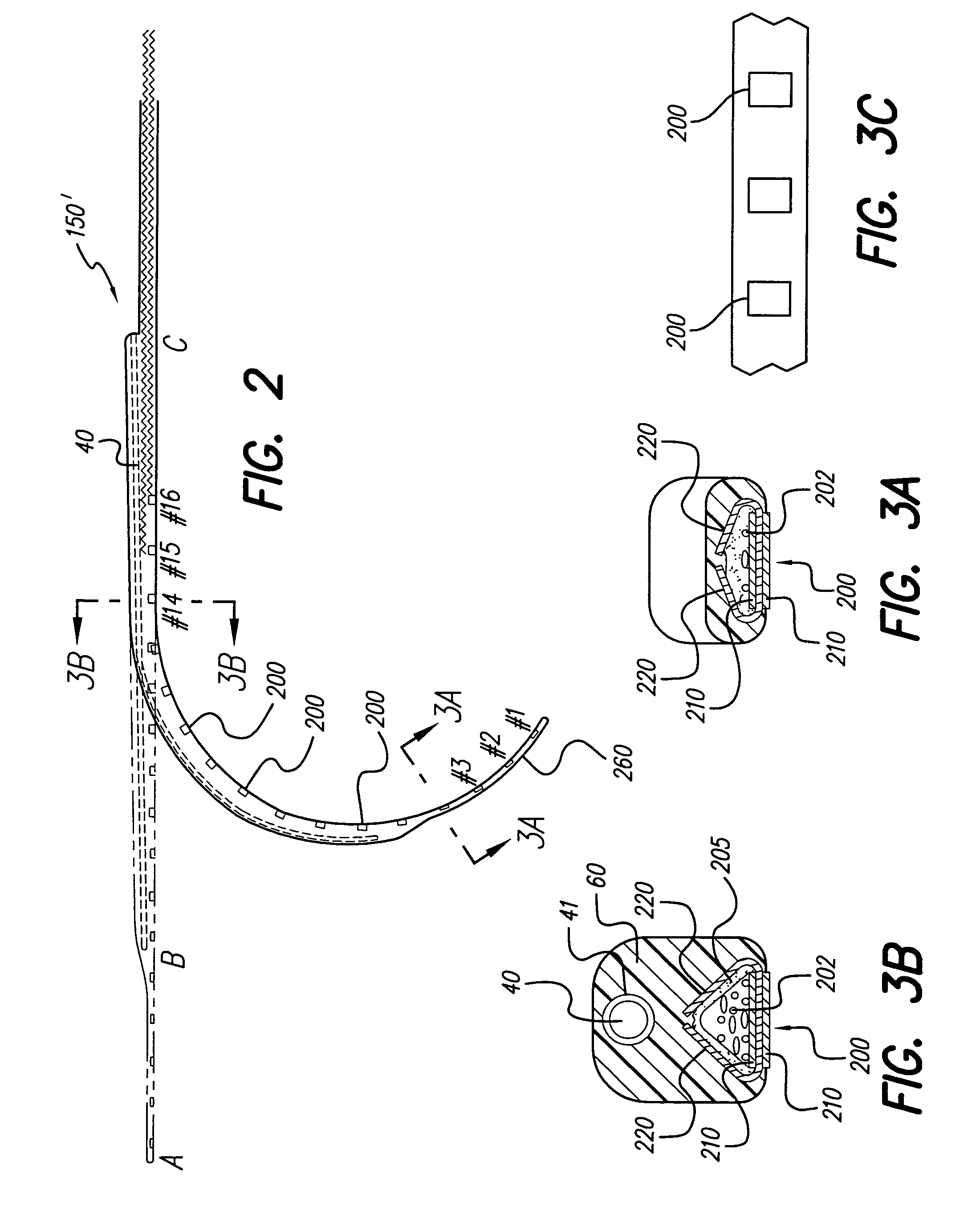
[0063]FIG. 1 shows one embodiment of the lead 150 made in accordance with the present invention. In a cochlear application, the lead 150 has an outer (l...


PUM


Abstract

A cochlear stimulation lead having a pre-curved electrode array is provided. The molding process provides memory to the curved part of the lead. The lead may be made having a stylet insertion channel that extends from a slightly curved or substantially straight section and into the highly curved section of the lead. Because high compliance is desired for the lead in cochlear stimulation applications, the compliance is controlled not only by the taper at the distal end of the lead and overall lead thickness, but also by choosing the material hardness of the lead carrier / covering and employing compliant zigzagged conductor wire. In addition, differential lead compliance / stiffness can be achieved by using a stiff tubing that forms part of the stylet insertion channel.

Description

[0001]The present application claims the benefit of U.S. Provisional Patent Application Ser. No. 60 / 412,253, filed 19 Sep. 2002, which application is herein incorporated by reference.BACKGROUND OF THE INVENTION[0002]The present invention relates to implantable stimulation devices, and, more particularly, to electrode arrays for stimulation of the cochlea. Electrode arrays consist of electrode contacts generally placed along one side of an elongate carrier so that when the array is implanted within one of the cochlear ducts such as the scala tympani, the electrode contacts are positioned in close proximity to the cells that are to be stimulated, allowing such cells to be stimulated with minimal power consumption.[0003]For purposes of clarity, as used herein, an implantable stimulating lead is a device that has one or more electrode contacts that deliver current to tissue to be stimulated. An electrode contact is that part of the stimulating device which is actually electrically condu...

Claims


Application Information

Patent Timeline
Patent Type & Authority Patents(United States)
IPC IPC(8): A61N1/05A61N1/36
CPCA61N1/0541A61N1/36032
Inventor KUZMA, JANUSZ A.SMITH, LANI A.THENAWARA, CHULADATTAHAZARD, STEVEN A.
Owner ADVANCED BIONICS AG
Why Eureka
Try Eureka