Automated planter

a planter and automatic technology, applied in the field of automatic planting, can solve the problems of limited work hours, high labor intensity of farmers, limited work hours, etc., and achieve the effect of minimal damage to the root structur

Inactive Publication Date: 2008-01-08
AUTOPLANTER
View PDF2 Cites 17 Cited by
  • Summary
  • Abstract
  • Description
  • Claims
  • Application Information

AI Technical Summary

Benefits of technology

[0022]Preferably, the planter further comprises stop means arranged to limit movement of the spacer member or members towards a located tray so as to prevent or limit compression of a root portion surface by the spacer member. Alternatively, engagement of the spacer member with the surface of the root portion itself can be used to limit downward movement of the spacer, enabling the fingers to be driven down, at its sides, so that they can enter the root portion, converge and grip the root ball.
[0059]Advantageously, the plant transport means may comprise two continuous tracks of holding ports, so that when the first track is static the second track may be moving. In this way, one track can be filled with a row of plants from the extraction means whilst the second track is transporting a row of plants to the planting device, thus reducing the down time of the system.

Problems solved by technology

In the past, such farming was extremely labour intensive.
Other disadvantages of involving humans include labour charges and limited work hours.
The need for human input means that this planting system suffers from the aforementioned problems.
However, in addition to requiring a large amount of labour, the use of drop chutes presents a further problem.
Again, the use of drop chute causes difficulties when trying to achieve even plant spacing.
Also, blockages can occur.
Subsequent handling of the plants, after they have been pushed out of the tray, poses yet further problems.
Additionally, pushing the plants out from the trays can damage their roots, and variations in root-ball density and consistency can lead to different plants being pushed out to different extents.
This can further complicate subsequent handling.

Method used


Image

  • Automated planter
  • Automated planter
  • Automated planter

Examples


Embodiment Construction

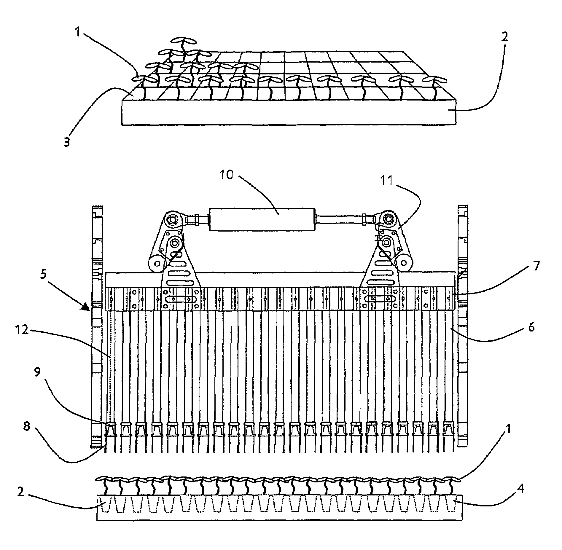
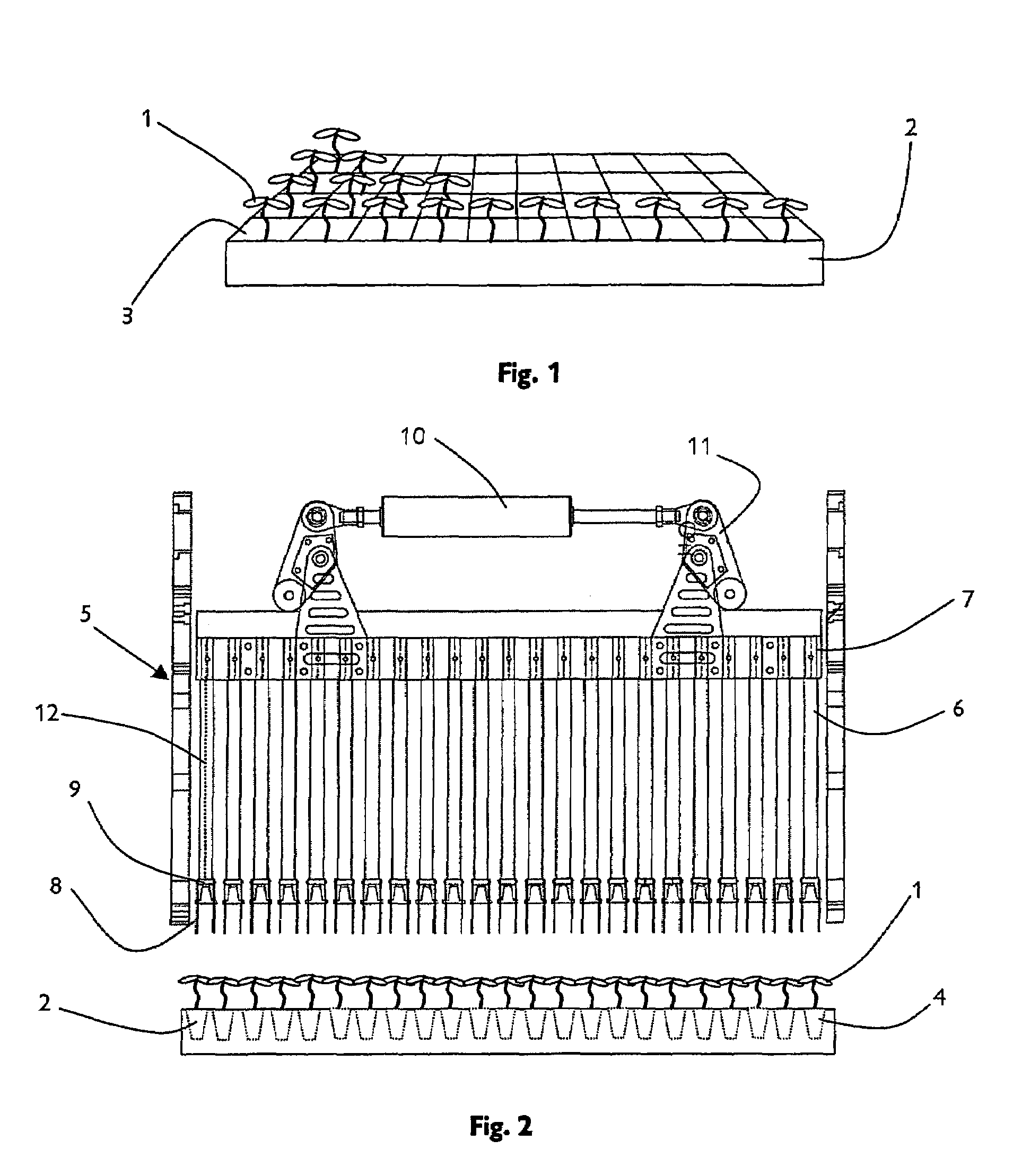
[0092]It is standard practice to grow plants 1 from seed in propagation trays 2. Such practice allows the farmer to easily control the plant's environment until it has grown to a suitable age. Propagation trays come in a range of sizes, and can have a range of cells 3 therein. The type of propagation tray used can depend on the type of plant being grown. In FIG. 1, a typical propagation tray 2 is illustrated; the tray is partially stocked with plants 1, each plant having its own individual cell 3.

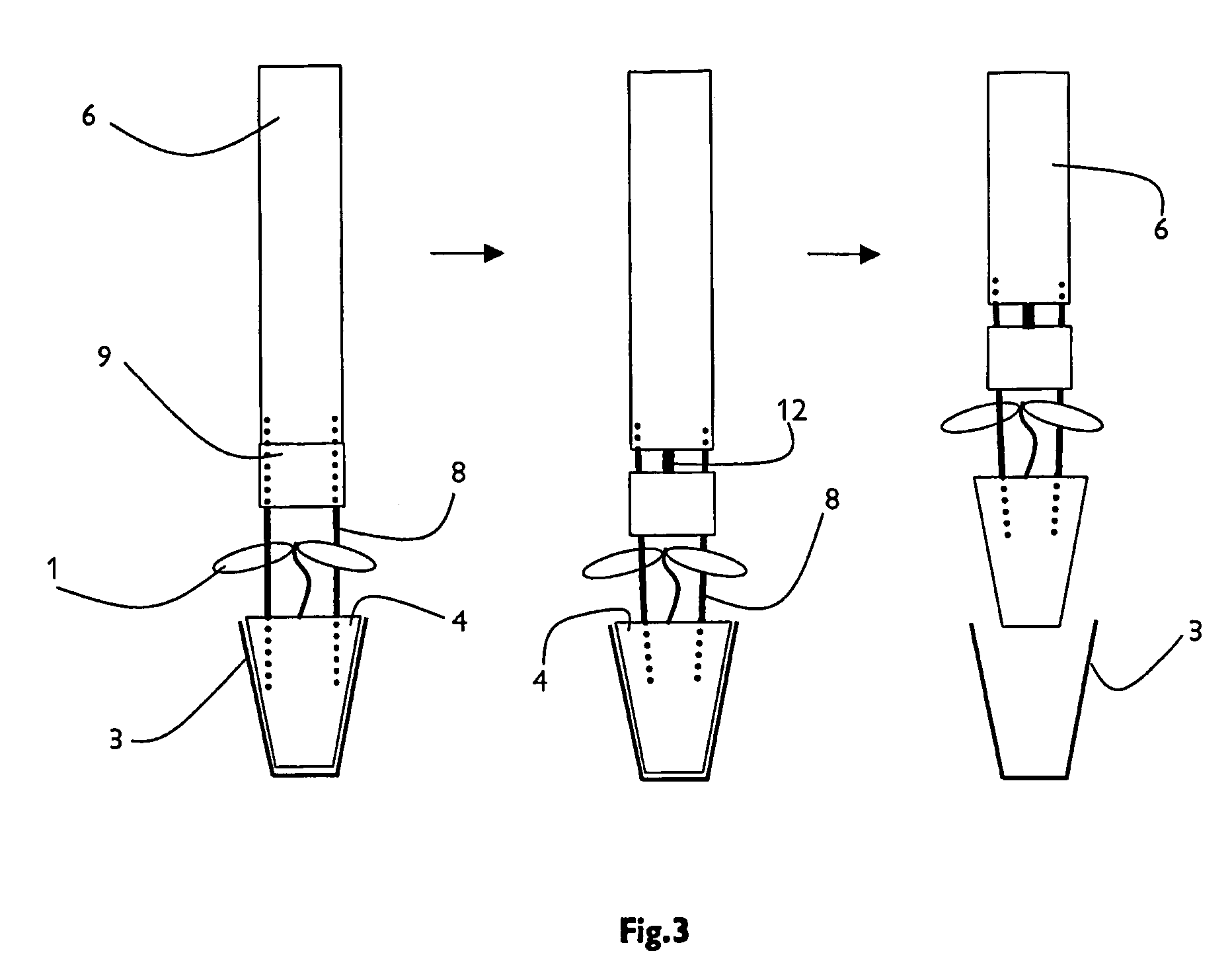
[0093]Certain embodiments of the invention carry out the task of extracting plants, from such propagation trays, and plant the extracted plants in the ground.

[0094]Extraction of the plants from their propagation trays, and transport of the plants to an automated planting device are functions which are automated in certain embodiments of the invention.

[0095]FIGS. 2 & 3 illustrate the components used, in a preferred embodiment, to automate the extraction function.

[0096]In FIG. 2, the alignmen...


PUM


Abstract

An automated planter includes a locating device arranged to locate a propagation tray; at least one plant extraction device adapted to pull a plant out of a propagation tray located by the locating device; and a delivery assembly arranged to receive a plant extracted by the at least one plant extraction device and deliver the received plant to the ground. The planter lifts the plants out of their cells in the tray by inserting fingers, which are caused to converge to pinch the root ball. A plant transport includes two tracks, such that one can be loaded while the other is transporting plants to the delivery assembly.

Description

FIELD OF THE INVENTION[0001]This invention relates to the field of automated planting, and more specifically to the planting of plants from a propagation tray.BACKGROUND OF THE INVENTION[0002]Agricultural farming is a vital component of the food supply system in any country. In the past, such farming was extremely labour intensive. However, over the years technology has been applied to automate various tasks and thus improve the efficiency of the farming as a whole.[0003]One area where machines have been particularly useful is in repetitive functions such as planting. In order for an individual plant (or crop) to enjoy optimum growing conditions, certain conditions must be met; one such condition is inter-plant spacing. Machines can be designed to provide constant spacing.[0004]Although automation of many farming functions has taken place, there are still aspects where a human interaction is preferable (e.g. where the plant may be damaged). In a semi-automated system, the most likel...

Claims


Application Information

Patent Timeline
Patent Type & Authority Patents(United States)
IPC IPC(8): A01C11/00A01G9/08A01G9/10
CPCA01C11/025A01G9/083A01G9/086Y10S47/901
Inventor FOUNTAIN, CHRISTOPHER GEORGEFOUNTAIN, NICHOLASFOUNTAIN, ROBIN CHARLES
Owner AUTOPLANTER
Why Eureka
Try Eureka