[0008]In a specific embodiment of the mounting bracket, the first traversing
mount and the second traversing
mount are flexibly coupled between the wall bracket and the display bracket, thereby enabling misalignment of the positions of the first traversing
mount and the second traversing mounts to adjust the
skew of the display bracket relative to the wall bracket. In another specific embodiment, the first traversing mount and the second traversing mount are flexibly coupled to enable rotation within a plane that is parallel to the wall on which the wall bracket is disposed. In another specific embodiment of the mounting bracket, the first traversing mount is flexibly connected to the first
actuator and the second traversing mount is flexibly connected to the second
actuator, thereby enabling misalignment of the positions of the first traversing mount and the second traversing mount to adjust the
skew of the display bracket relative to the wall bracket.
[0009]In a specific embodiment of the mounting bracket, the first
actuator and the second actuator are threaded rods that engage the first traversing mount and the second traversing mount, respectively. The threaded rods extend to a
peripheral location on the mounting bracket, thereby enabling access for actuation thereof by a user. In another specific embodiment, the display bracket is configured as a first portion and a second portion that are independently supported, thereby enabling adjustment of their spacing
adaptation to the mounting configuration of the
flat panel display.
[0010]In a specific embodiment of the mounting bracket, the first traversing mount and the second traversing mount are removably disposed between the wall bracket and the display bracket. In a refinement, the mounting bracket also includes a horizontal mounting
flange disposed to removably engage the first traversing mount and the second traversing mount, thereby enabling adjustment of the horizontal position of the display bracket relative to the wall bracket. In another refinement, the mounting bracket further includes a mount lock coupled to selectively lock the position of the display bracket to the wall bracket, and, the mount lock is selectively actuated by a lock actuator. In a further refinement, the mount lock is positioned to urge the first traversing mount and the second traversing mount against the horizontal mounting
flange, thereby preventing disengagement there from. The lock actuator may be a
threaded rod that engages the mount lock and extends to a
peripheral location on the mounting bracket. The lock actuator may engage the first actuator or the second actuator.
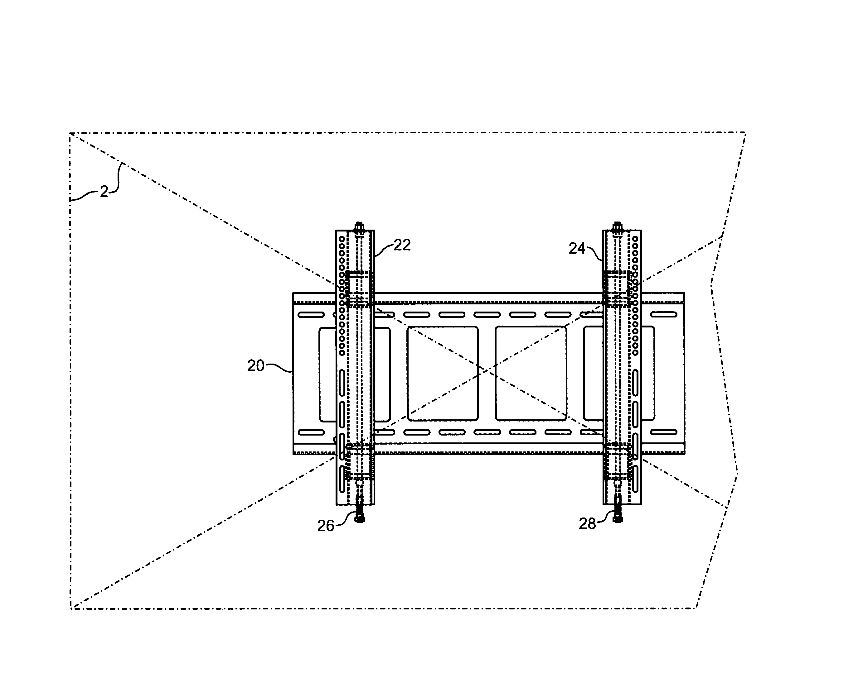
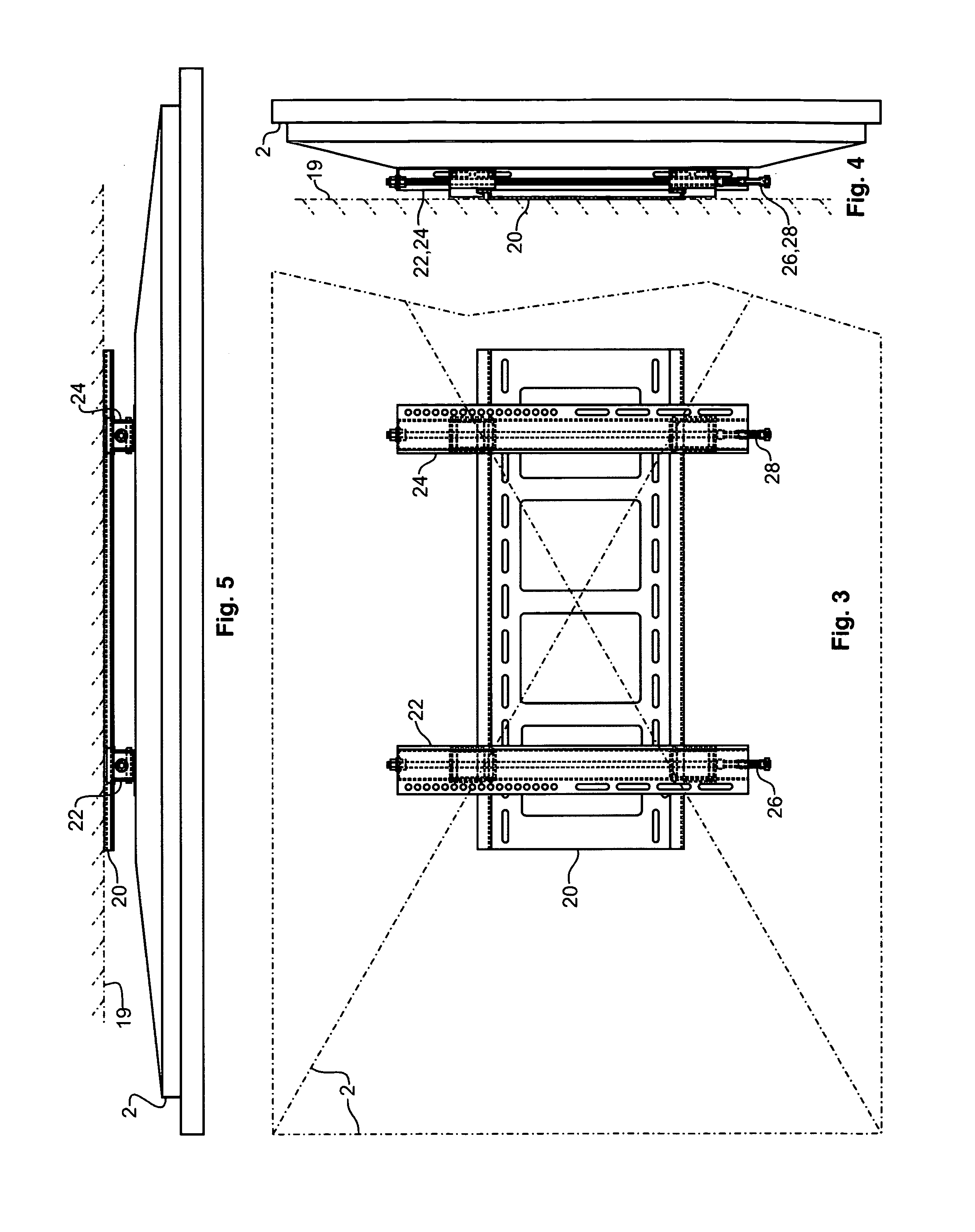
[0011]The present invention also teaches a mounting bracket apparatus for adjustably supporting a flat panel display from a wall configured as follows. A wall bracket has a first horizontal
flange aligned in parallel with a second horizontal flange. A first display bracket has a first traversing mount driven along a first linear axis and engaged with a first
threaded rod actuator that extends to a
peripheral location on the mounting bracket. The first traversing mount has a curved extension formed to supportively engage the first horizontal flange and enable rotation of the first display bracket along a
plane parallel to the wall on which the wall bracket is mounted. The first display bracket further includes a first mount lock slidably positioned along the first
threaded rod actuator and aligned to be urged against the second horizontal flange by a first lock actuator that is concentric to and engaged with the first threaded rod, and that extends to a peripheral location on the mounting bracket. The mounting bracket also includes a second display bracket that has a second traversing mount driven along a second linear axis and engaged with a second threaded rod actuator that extends to a peripheral location on the mounting bracket. The second traversing mount has a curved extension formed to supportively engage the first horizontal flange and enable rotation of the second display bracket along the
plane parallel to the wall on which the wall bracket is mounted. The second display bracket further includes a second mount lock slidably positioned along the second threaded rod actuator that is aligned to be urged against the second horizontal flange by a second lock actuator that is concentric to and engaged with the second threaded rod, and that extends to a peripheral location on the mounting bracket. The first display bracket and the second display bracket are independently positionable along the first horizontal flange, thereby enabling adjustment of the horizontal position of the flat panel display, and further enabling adjustment of the spacing between the first display bracket and the second display bracket to allow
adaptation to the mounting configuration of the flat panel display.

