
Articulated bearing supports for laser resonators

Inactive Publication Date: 2008-01-08
TRUMPF LASERTECHN
View PDF15 Cites 37 Cited by
  • Summary
  • Abstract
  • Description
  • Claims
  • Application Information

AI Technical Summary

Benefits of technology

The solution ensures the laser resonator is securely mounted and oriented without the need for additional vertical safety, enabling reliable operation by integrating the vertical securing mechanism into the bearing support design, thus preventing lifting or springing issues.

Problems solved by technology

The laser resonator is not to be operated with the transport safety detached, but it is sometimes forgotten to detach the vertical safety again after transport, thus leading to errors.

Method used


Image

  • Articulated bearing supports for laser resonators
  • Articulated bearing supports for laser resonators
  • Articulated bearing supports for laser resonators

Examples


Embodiment Construction

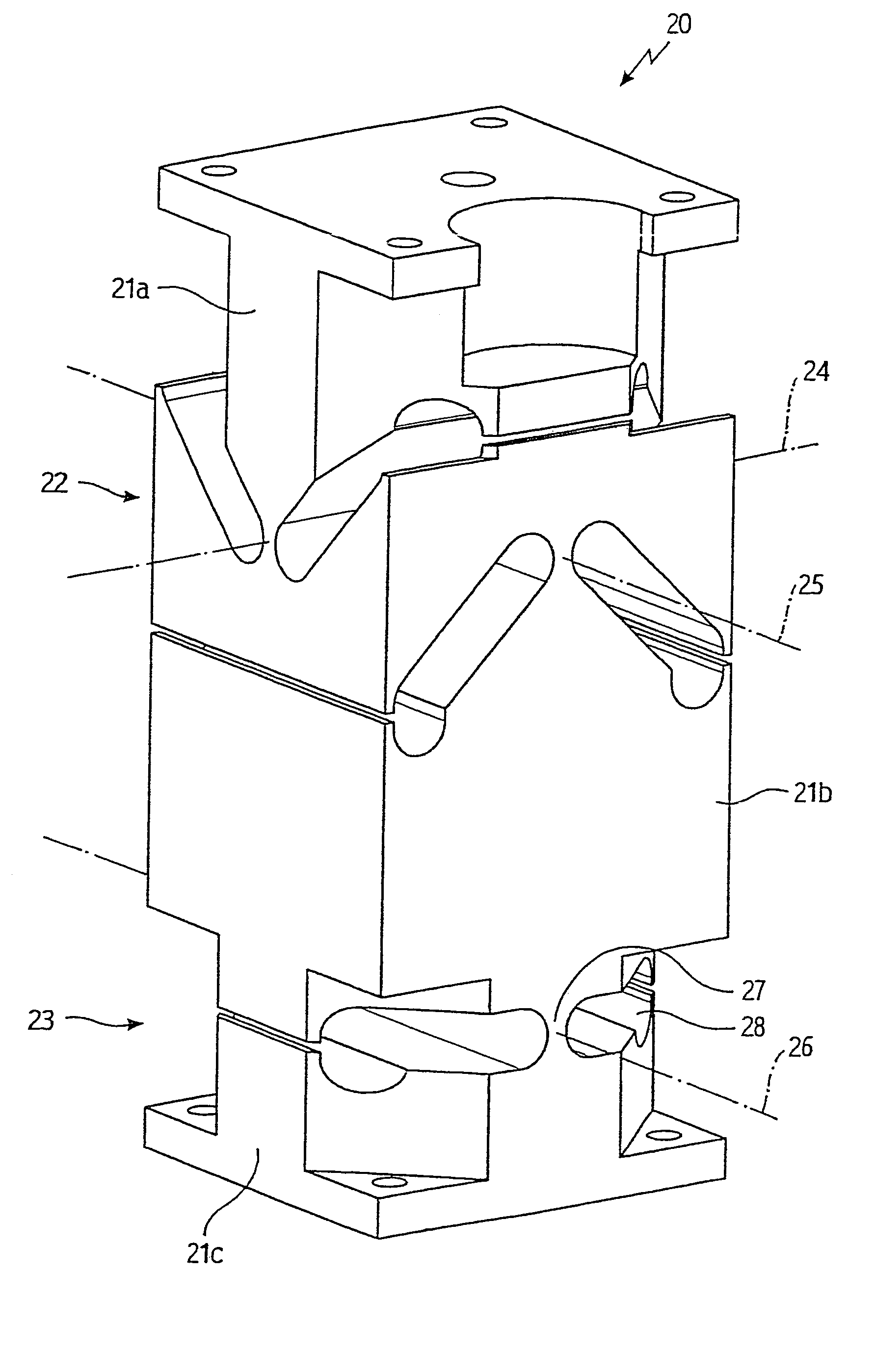
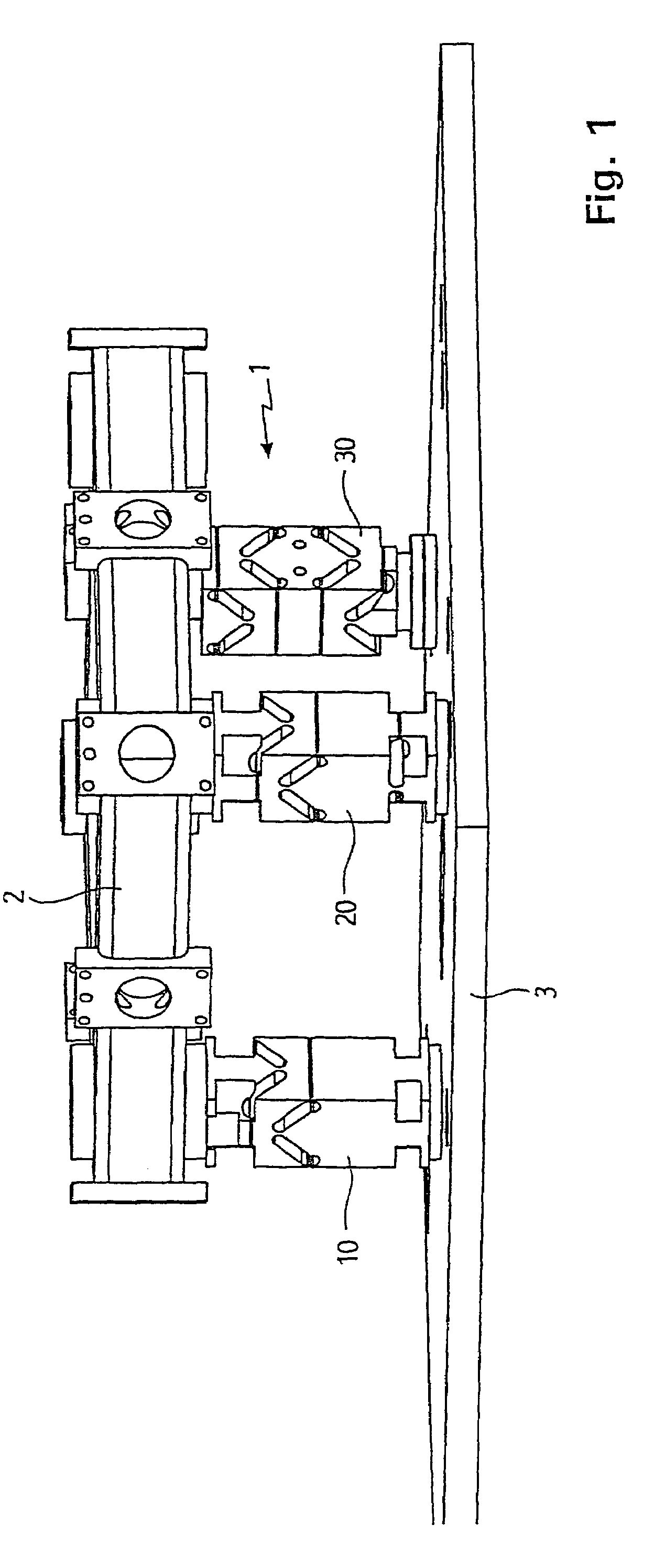
[0045]The bearing support assembly 1 shown in FIG. 1 for a square-folded laser resonator comprises three one piece bearing supports 10, 20, 30 attached to a base plate 3 and on which the resonator frame 2 sits. The bearing support 10 corresponds in function to a fixed bearing with two rotational degrees of freedom, the bearing support 20 to a one-dimensional movable bearing with two rotational degrees and one translational degree of freedom, and the bearing support 30 to a two-dimensional movable bearing with two rotational and two translational degrees of freedom.

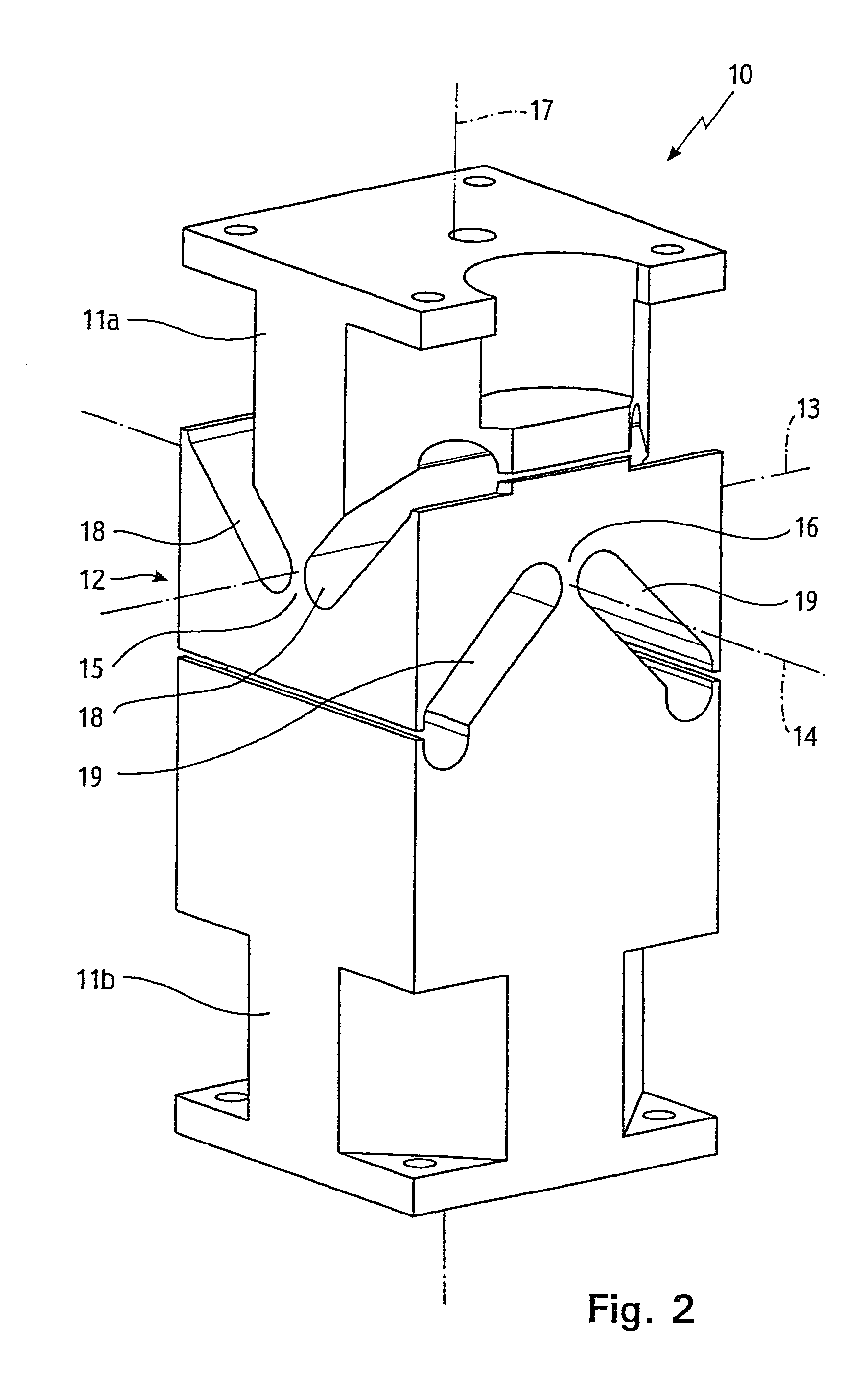
[0046]The bearing support 10 shown in FIG. 2 comprises an upper support section 11a, having a support platform with a horizontal surface to which the laser resonator 2 is attached, and a lower support section 11b attached on the bottom to the base plate 3. The two support sections 11a, 11b are connected together as one piece by a defiectable joint 12 able to tilt all around. The deflection joint 12 has two horizontal tilt ...


PUM


Abstract

In a bearing support (10) for a laser resonator, adjacent support sections (11a, 11b) are directly and undetachably connected to each other by an articulated deflectable joint (12). An additional vertical safety on the bearing support is no longer necessary since the two support sections (11a, 11b) are already held together in a vertically secure manner by the articulated joint (12).

Description

CROSS REFERENCE TO RELATED APPLICATION[0001]The present application is a continuation of U.S. patent application Ser. No. 10 / 173,350 filed Jun. 14, 2002 now abandoned.BACKGROUND OF THE INVENTION[0002]The invention relates to a bearing support, in particular for a laser resonator, with at least two support sections and an articulated joint provided between sections, and a corresponding bearing support assembly with such bearing supports.[0003]To allow the horizontal shifts of a laser resonator—occurring, e.g., due to temperature changes or accelerations—in all directions, in a known bearing assembly the laser resonator is connected with a base plate by three bearing supports, namely by a four-way bearing support, a three-way bearing support and a two-way bearing support. The four-way bearing support is designated as a fixed bearing support and has two rotational degrees of freedom and no translational degree of freedom. The three-way bearing support with two rotational and one transl...

Claims


Application Information

Patent Timeline
Patent Type & Authority Patents(United States)
IPC IPC(8): F16M13/00G01M11/04H01S3/02
CPCG01M11/04H01S3/02
Inventor HACKER, MICHAELANDREASCH, WOLFGANG
Owner TRUMPF LASERTECHN
Learn More