Ergonomic router assembly

a router and ergonomic technology, applied in the field of ergonomically designed power tools, can solve the problems of limiting the effective control of the router, increasing fatigue levels, and unused space, and achieve the effects of reducing stress on the parts of the operator, comfortable gripping an object, and thin handl

Inactive Publication Date: 2008-01-08
BLACK & DECKER INC
View PDF196 Cites 11 Cited by
  • Summary
  • Abstract
  • Description
  • Claims
  • Application Information

AI Technical Summary

Benefits of technology

[0007]Accordingly, the present invention is directed to a router with an ergonomically designed base and motor casing. Ergonomic design features function to relieve stress on the parts of an operator being used to operate a machine. For instance, providing a thinner handle enables the hand to more comfortably grip an object. This in turn relieves stress on the muscles used for gripping which in turn decreases fatigue levels in those muscles and increases overall performance of the muscles. In the present invention, an ergonomically designed motor casing provides an overall narrower profile, reducing the amount of unused space between the interior of the walls of the motor casing and the windings of the motor. Additionally, a base with a hand cradle assembly is provided for engaging the side of the hand of an operator. These features provide support to the hand of the operator which relieves stress on the muscles and allows the operator to firmly grasp the router with one hand thus decreasing fatigue levels as compared to those routers which require both hands of the operator to be engaged for control over the router.
[0008]The present invention, further enables the hand of the operator to engage with a grip assembly which provides additionally ergonomic functionality. The grip assembly is designed to incorporate materials which engage the hand of the operator with material as opposed to the metal of the motor casing. The material is designed to flexibly engage the hand of the operator and provide absorption of operational stresses. Such flexible engagement may comprise a grip zone which provides a flexible or cushioned gripping region for the hand of the operator. Operational stress absorption may be provided by the choice of materials employed on the grip assembly, for instance a firmer material may provide a firmer grip region but translate stresses, such as vibrations, at a higher rate than a more flexible material.
[0009]It is an object of the present invention to provide a router which is ergonomically designed to increase operator comfort and control when operating the router. It is a further object of the present invention to reduce muscle fatigue and the concomitant productivity decrease experienced by users of typical routers.

Problems solved by technology

These motor housings, surround the motor, and typically leave unused space between the interior of the walls of the housing and the windings of the motor.
This may result in a large housing of the router, which may be difficult for the user to firmly grasp, thus, limiting the effective control over the router.
Further, the demands placed on the hands of the user, in grasping the large motor housing, may increase fatigue levels which may decrease productivity.
Unfortunately, attempts to construct more ergonomically configured routers have fallen short of the goal of providing a significantly easier to operate router.

Method used


Image

  • Ergonomic router assembly
  • Ergonomic router assembly
  • Ergonomic router assembly

Examples


Embodiment Construction

[0023]Reference will now be made in detail to the presently preferred embodiments of the invention, examples of which are illustrated in the accompanying drawings.

[0024]Referring generally now to FIGS. 1A through 6, exemplary embodiments of the present invention are shown.

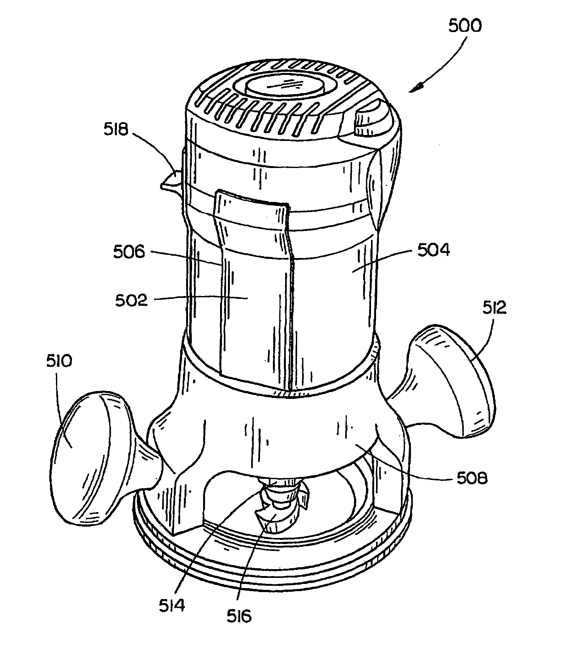
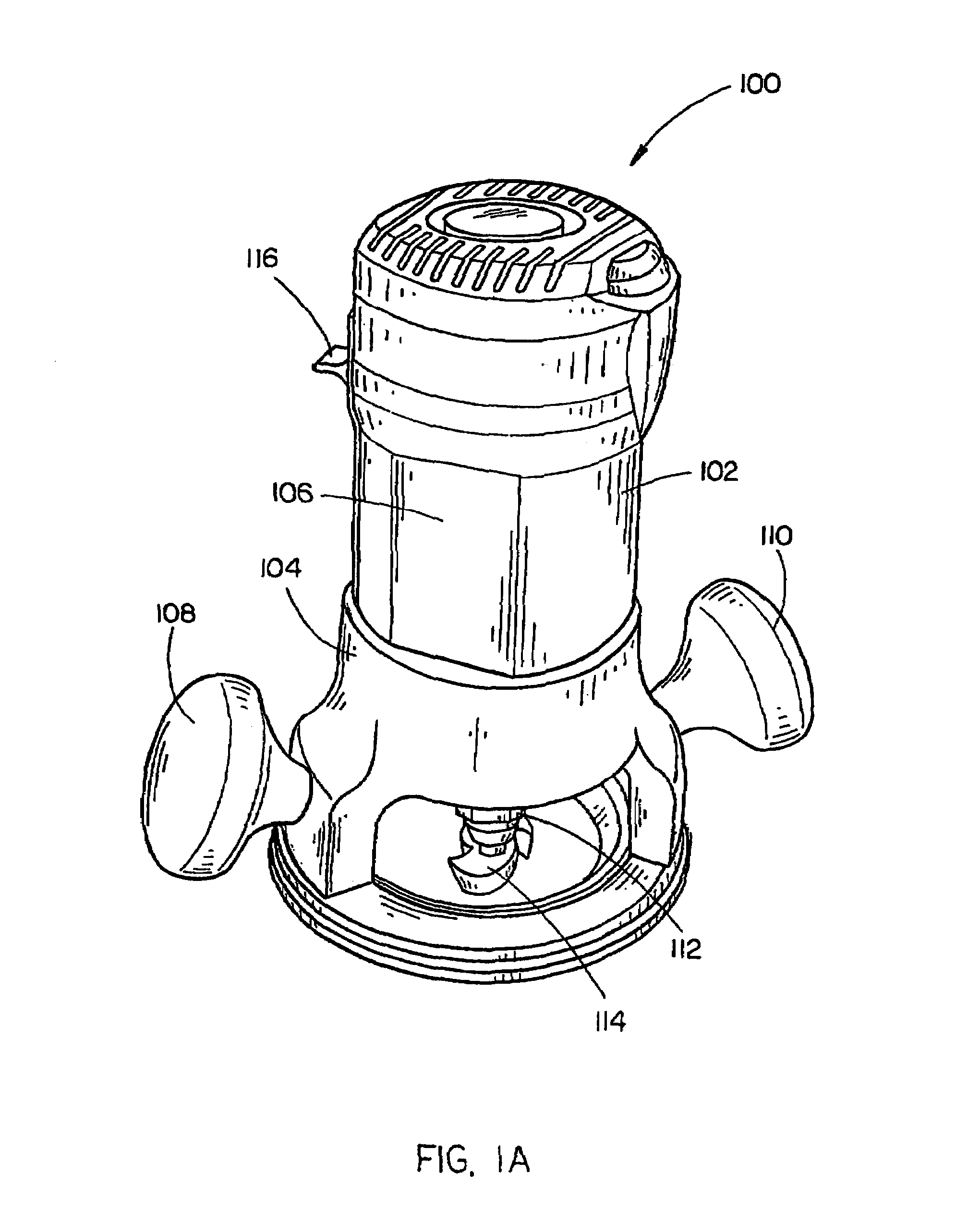
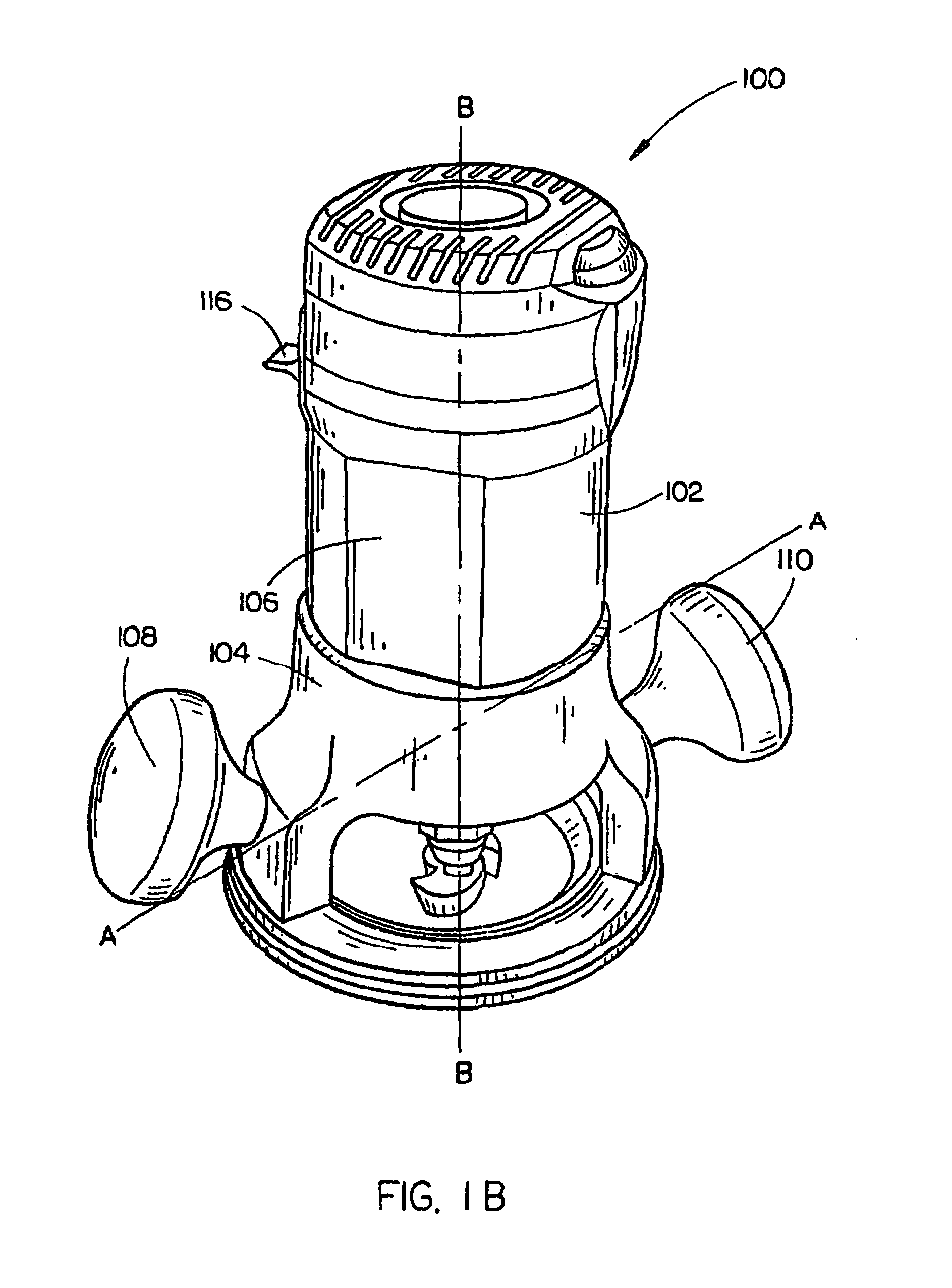
[0025]A router assembly 100 including a motor casing 102 coupled with a base assembly 104, is shown in FIGS. 1A through 1D. The motor casing 102 is generally configured to surround a motor. The motor casing 102 is disposed with a first grip zone 106 of a grip assembly 105. The grip assembly, in the current embodiment, includes the first grip zone 106 disposed on the motor casing 102 in a location proximal to a first knob handle 108 coupled with the base assembly 104. The base assembly 104 is coupled with the first knob handle 108 and a second knob handle 110.

[0026]In the preferred embodiment, the grip assembly is integrally defined within the configuration of the motor casing102. In alternative embodiments, the gri...


PUM

PropertyMeasurementUnit
ninety degree angleaaaaaaaaaa
angleaaaaaaaaaa

Abstract

An ergonomically designed router assembly includes a base assembly coupled with a motor casing including a grip assembly which provides an overall narrower profile to the router assembly. The grip assembly may relieves stress on the muscles and allows the operator to more securely grasp the router with one hand thus decreasing fatigue levels as compared to those routers which require both hands of the operator to be engaged for control over the router.

Description

CROSS REFERENCE TO RELATED APPLICATION[0001]The present application is a continuation-in-part under 35 U.S.C. §120 of the U.S. application Ser. No. 10 / 686,300, filed on Oct. 15, 2003 now abandoned, which claims the benefit under 35 U.S.C. §119(e) of the U.S. Provisional Application Ser. No. 60 / 418,510, filed on Oct. 15, 2002, and claims the benefit under 35 U.S.C. §119(e) of the U.S. Provisional Application Ser. No. 60 / 467,169, filed on May 1, 2003. Said U.S. Provisional Application Ser. No. 60 / 418,510 and said U.S. Provisional Application Ser. No. 60 / 467,169 are herein incorporated by reference in their entireties.[0002]The present application herein incorporates U.S. application Ser. No. 10 / 384,510, filed Mar. 7, 2003, and U.S. application Ser. No. 10 / 458,167, filed Jun. 10, 2003 by reference in their entireties.FIELD OF THE INVENTION[0003]The present invention generally relates to the field of power tools, and particularly to an ergonomically designed power tool, such as a router...

Claims


Application Information

Patent Timeline
Patent Type & Authority Patents(United States)
IPC IPC(8): B23C1/20
CPCB27C5/10Y10T409/306608
Inventor COOPER, RANDY G.ETTER, MARK A.GRIFFIN, GREG K.ALLEN, GINGER L.KILBOURNE, DERRICK
Owner BLACK & DECKER INC
Why Eureka
Try Eureka