Electrostatic discharge enhanced charge contact design

Active Publication Date: 2008-01-08
VTECH TELECOMM
View PDF17 Cites 14 Cited by
  • Summary
  • Abstract
  • Description
  • Claims
  • Application Information

AI Technical Summary

Benefits of technology

[0019]One embodiment of the invention is an electrical contact that reduces electrostatic discharge in electronic devices. The electrical contact includes a contact head, a contact pin, a body, a electrical connection plate, and a spring. The contact head is made of a nonconductive material. The contact pin is made of a conductive material. The contact pin includes a top end, a stem, and a terminal point. The contact pin is embedded within the contact head so as to provide an electrical p

Problems solved by technology

The discharge may result in damage to the circuitry in either or both of handset 12 and base unit 11.
Such protective circuitry or other structures (mechanical and/or electrical) often significantly add to the complexity and cost, as well as the physical size, of the telephone components.
Nevertheless, there may exist non-uniformities in the spring force of individual charge contacts due to various fabrication and quality control issues.
Such thin sheet metal construction for known resilient contact supp

Method used


Image

  • Electrostatic discharge enhanced charge contact design
  • Electrostatic discharge enhanced charge contact design
  • Electrostatic discharge enhanced charge contact design

Examples


Example

DETAILED DESCRIPTION OF THE DRAWINGS

[0057]While this invention is susceptible of embodiment in many different forms, there is shown in the drawings and will be described herein in detail, a specific embodiment, with the understanding that the present invention is to be considered as an exemplification of the principles of the invention and is not intended to limit the invention to the embodiment illustrated.

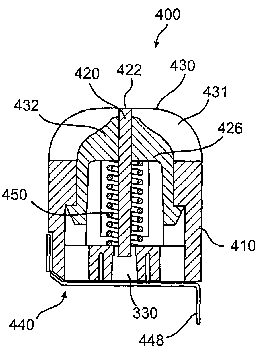
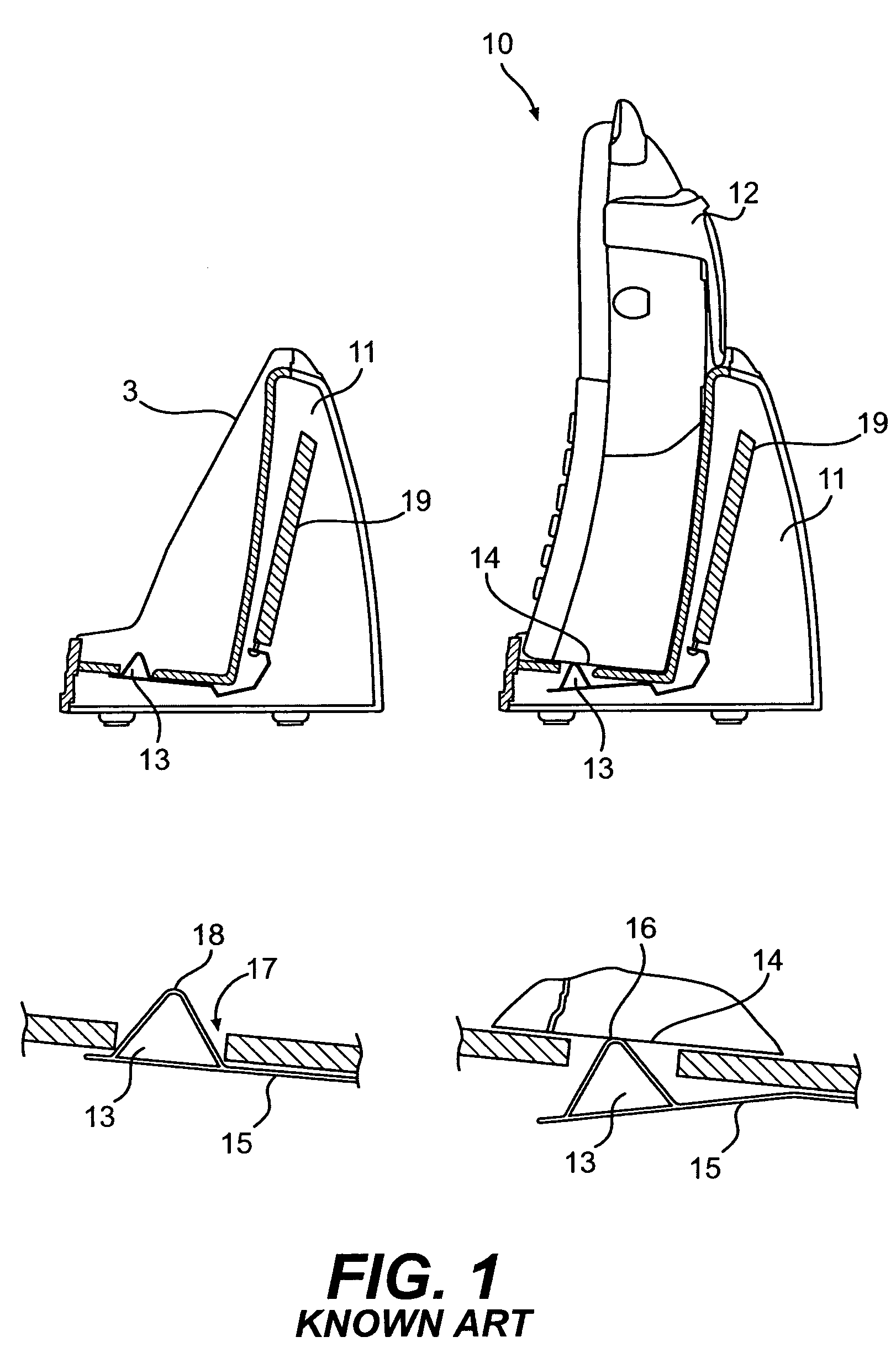
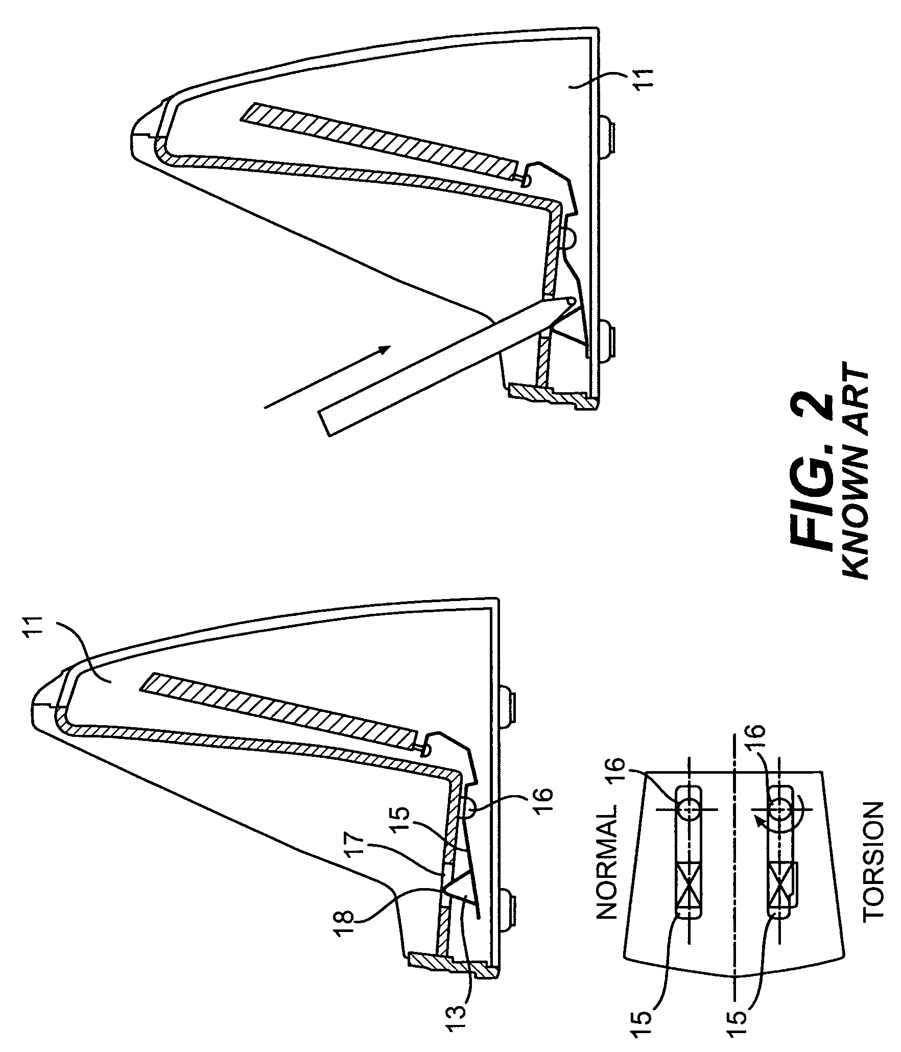
[0058]The preferred embodiment of the invention is directed to an electrical contact construction. The electrical contact incorporates a movable metal connection component. The moveable component is resiliently mounted within an insulating body. In the context of an electronic device (e.g., a cordless telephone) that includes a portable unit (e.g., the handset) and base (e.g., the base unit of the cordless telephone), the electrical contact of the invention can be incorporated, e.g., as a component of the base. An electrically conducting path from a contact head of the electrical...


PUM


Abstract

The present invention is directed to an electrical contact that incorporates a movable metal connection component such as a contact pin. The metal connection component is mounted within an insulating body. An electrically conducting path, from a contact head of the metal connection component to an interior of a base chassis is created only when a handset has been positioned within a cradle cavity of the base.

Description

CROSS-REFERENCE TO RELATED APPLICATION[0001]This application claims the benefits of U.S. Provisional Patent Application No. 60 / 381,949 filed on May 20, 2002, which is incorporated herein by reference in its entirety.BACKGROUND OF THE INVENTION[0002]1. Field of the Invention[0003]The present invention relates generally to electrical contact constructions and, more particularly, to electrical contact constructions for cordless telephone handset apparatus.[0004]2. Background of the Invention[0005]FIG. 1 is a schematic diagram showing a known cordless telephone. Conventional cordless telephone 10 includes base unit 11 and handset 12. The left half of FIG. 1 shows base unit 11 without handset 12 placed within it. The right half of FIG. 1 shows handset 12 rested within base unit 11.[0006]Base unit 10 includes battery charging equipment 19 and a cradle cavity that is configured to receive handset 12. The cradle cavity has electrical contacts 13 that are suitably disposed within the cradle ...

Claims


Application Information

Patent Timeline
IPC IPC(8): H01R13/24H01R13/648H01R13/70H02J7/00
CPCH01R13/2421H01R13/6485H02J7/0044H01R13/701H01R2201/16
Inventor CHAN, CHAUK HUNGCAI, YONG YANGPANG, CHU ZHU
Owner VTECH TELECOMM
Why Eureka
Try Eureka