Portable wound treatment apparatus

a wound treatment and portable technology, applied in the field of wound healing, can solve the problems of less easy to determine the pressure prevailing at the wound site being treated, and achieve the effects of easy removal and replacement, less easy to determine the pressure prevailing, and increased speed

Inactive Publication Date: 2008-01-08
KCI LICENSING INC
View PDF142 Cites 306 Cited by
  • Summary
  • Abstract
  • Description
  • Claims
  • Application Information

AI Technical Summary

Benefits of technology

[0007]Typically, the housing will have a curved surface on the side intended to be supported against the person's body so as to make the apparatus more comfortable to wear. In addition, controls and indicators indicating the status of the treatment being applied to the wound are preferably located on the upper side of the housing so that the patient can easily see, e.g., the level of suction pressure being applied and the program for such treatment.
[0008]The suction pump is conveniently driven by an electric motor and batteries for such motor may be contained within the housing. However, it is generally more convenient to provide a separate housing for the batteries since these can be placed on the belt or harness in such a way as to balance the weight of the housing, preferably in a housing shaped similarly to the housing for the pump and canister. The canister should be removably mounted within the housing, e.g. by means of a latch or release mechanism, so that the canister can be readily removed and replaced when full.
[0009]In a portable therapeutic apparatus (in contrast with a static apparatus of the kind described in the above PCT application which cannot be easily carried by the patient), it is less easy to determine the pressure prevailing at the wound site being treated. This is because the pressure will depend, in part, upon the hydrostatic height between the pump and the wound being treated and this height may vary during the treatment, depending upon the patient's movements. The apparatus in accordance with the invention overcomes this problem by providing an additional conduit connecting the wound site or an area close thereto to a pressure-detecting means, preferably located in the housing. The pressure-detecting means can be linked to a microprocessor programmed to maintain such pressure within a predetermined range irrespective of the movement of the patient. This can be done by, for example, signaling the pump to increase its speed where the hydrostatic pressure increases between the pump and the wound site or, conversely, reducing its speed where the hydrostatic pressure is reduced. This feature can also be used in a static therapeutic apparatus of the kind described in the above-mentioned PCT application.
[0010]In the apparatus described in the above PCT application, the level of liquid in the canister is monitored by capacitance measurement. It has now been found that a simpler way of determining when the canister is filled is by measuring or detecting the pressure drop across the canister. The pressure drop can be increased by providing a filter barrier in the region of the outlet end of the canister. Thus, when the liquid reaches a level within the canister so as to substantially occlude the filter, a sharp pressure change occurs in the conduit between the canister and the pump. By monitoring this pressure change, the point at which the canister is filled can be accurately determined.

Problems solved by technology

In a portable therapeutic apparatus (in contrast with a static apparatus of the kind described in the above PCT application which cannot be easily carried by the patient), it is less easy to determine the pressure prevailing at the wound site being treated.

Method used


Image

  • Portable wound treatment apparatus
  • Portable wound treatment apparatus
  • Portable wound treatment apparatus

Examples


Embodiment Construction

[0021]Although those of ordinary skill in the art will readily recognize many alternative embodiments, especially in light of the illustrations provided herein, this detailed description is exemplary of the preferred embodiment of the present invention, the scope of which is limited only by the claims appended hereto.

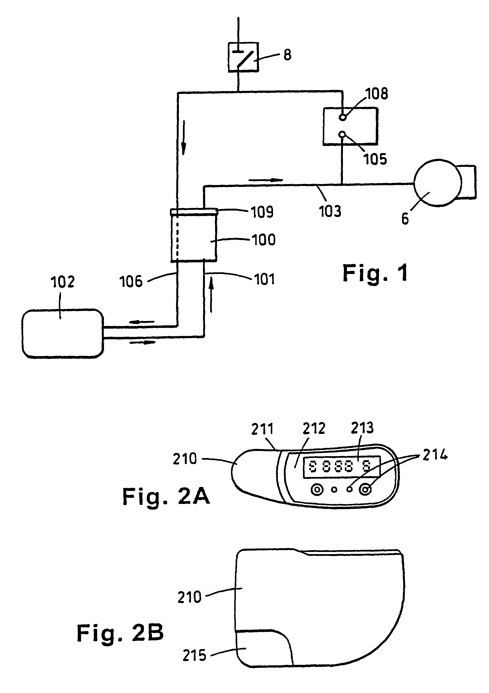
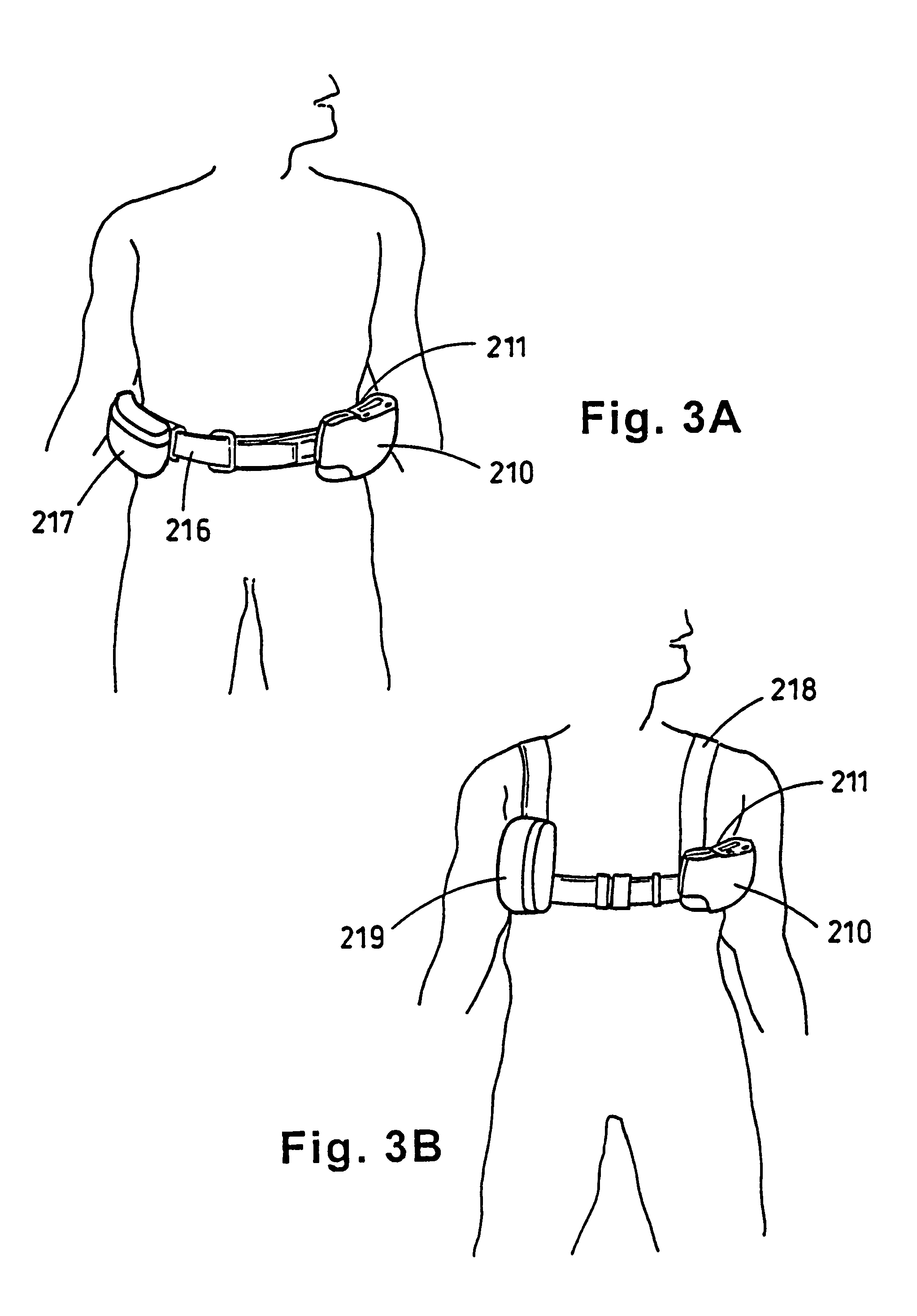
[0022]Referring to the drawings, the portable therapeutic apparatus comprises a housing 210 (best shown in FIGS. 2A and 2B), having rounded corners and a side 211 which is concavely curved in order to fit comfortably to the wearer's body. The shaping of the housing with curved surfaces is to avoid sharp corners or edges that could dig in to the user or his caregiver. The upper surface 212 is generally flat and has an LCD screen 213 on which details such as applied pressure can be displayed. Control buttons 214 are provided to adjust pressures and treatment intervals. Provision is made for housing a canister within the housing and a snap release cover 215 is arranged for...


PUM


Abstract

A portable wound treatment apparatus, for stimulating the healing of superficial wounds, comprises a housing containing a suction pump and a canister for containing fluids drawn from the wound. The housing is supported on a harness or belt worn by the patient. The canister is connected to a porous wound dressing at the wound site via a plurality of tubes, a multi-lumen tube or a combination thereof. A rechargeable battery pack may be incorporated within the housing or externally thereto. The external battery pack may be shaped to balance the housing on the harness or belt. Pressure transducers are provided to monitor and report pressures at the wound site or internal to the canister. Monitored pressures may also be utilized to determine the filled state of the canister and, thereafter, either report this state to the operator or automatically discontinue suction from the wound, or both.

Description

RELATED APPLICATIONS[0001]This application is a continuation of U.S. patent application Ser. No. 09 / 078,223 filed May 13, 1998 now U.S. Pat. No. 6,142,982, which is a continuation of PCT international application Serial No. PCT / GB96 / 02802 filed Nov. 14, 1996, which designates the United States and claims priority to British patent application No. 9523253.4 filed Nov. 14, 1995. By this reference, the full disclosures, including the drawings and claims, of U.S. patent application Ser. No. 09 / 078,223; PCT international application Serial No. PCT / GB96 / 02802; and British patent application No. 9523253.4 are incorporated herein as though each were now set forth in their respective entirety.FIELD OF THE INVENTION[0002]The present invention relates to the healing of wounds. More particularly, the invention relates to an apparatus for stimulating the healing of superficial wounds.BACKGROUND OF THE INVENTION[0003]PCT Application No. GB95 / 01983 (WO 96 / 05873) describes apparatus for stimulating...

Claims


Application Information

Patent Timeline
Patent Type & Authority Patents(United States)
IPC IPC(8): A61M27/00A61M1/00A61F13/00
CPCA61M1/0023A61M1/0052A61M1/0088A61M27/00A61M1/0049A61M1/0056A61M2205/15A61M2205/18A61M2205/3344A61M2205/3351A61M2205/3379A61M2205/581A61M2205/583A61M2205/8206A61M2209/088Y10S604/902A61M1/0037A61M1/75A61M1/784A61M1/78A61M1/79A61M1/80A61M1/984A61M1/982A61M1/82A61M1/915A61M1/732A61M1/96
Inventor HUNT, KENNETH WILLIAMHEATON, KEITH PATRICK
Owner KCI LICENSING INC
Why Eureka
Try Eureka