
Medium access control for retro-reflectors

a technology of access control and retro-reflector, which is applied in the field of communication, can solve the problem that the modulation of retro-reflectors does not provide a flexible access control method for controlling communications

Active Publication Date: 2008-01-08
RAYTHEON BBN TECH CORP
View PDF19 Cites 28 Cited by
  • Summary
  • Abstract
  • Description
  • Claims
  • Application Information

AI Technical Summary

Benefits of technology

This patent describes a method for controlling communications in systems that use retro-reflectors. The method involves receiving a first frame in an incoming beam and creating a second frame in a reflected beam that is closely aligned with the incoming beam. The first and second frames include medium access control information. The patent also describes devices that can send and receive incoming beams, as well as a system that includes a probe device and a group of retro-reflector devices. The technical effects of this patent include improved communication control and more efficient use of retro-reflectors in communication systems.

Problems solved by technology

However, existing communications systems that employ modulating retro-reflectors do not provide a flexible access control method for controlling communications among a probe device and a group of retro-reflectors, such that each of the retro-reflectors may receive schedule information regarding when respective retro-reflectors may be interrogated for data or may receive data.

Method used


Image

  • Medium access control for retro-reflectors
  • Medium access control for retro-reflectors
  • Medium access control for retro-reflectors

Examples


Embodiment Construction

[0016]The following detailed description of the invention refers to the accompanying drawings. The same reference numbers in different drawings may identify the same or similar elements. The following detailed description does not limit the invention. Instead, the scope of the invention is defined by the appended claims and equivalents.

Operating Environment

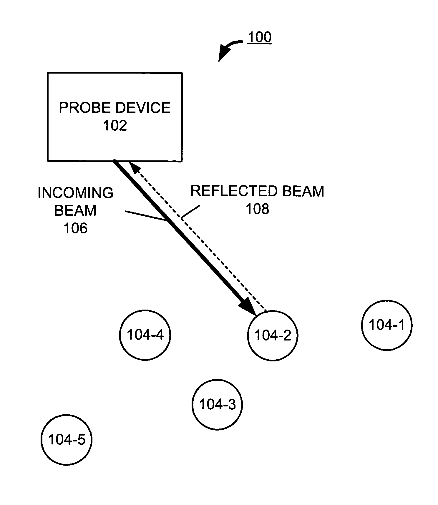
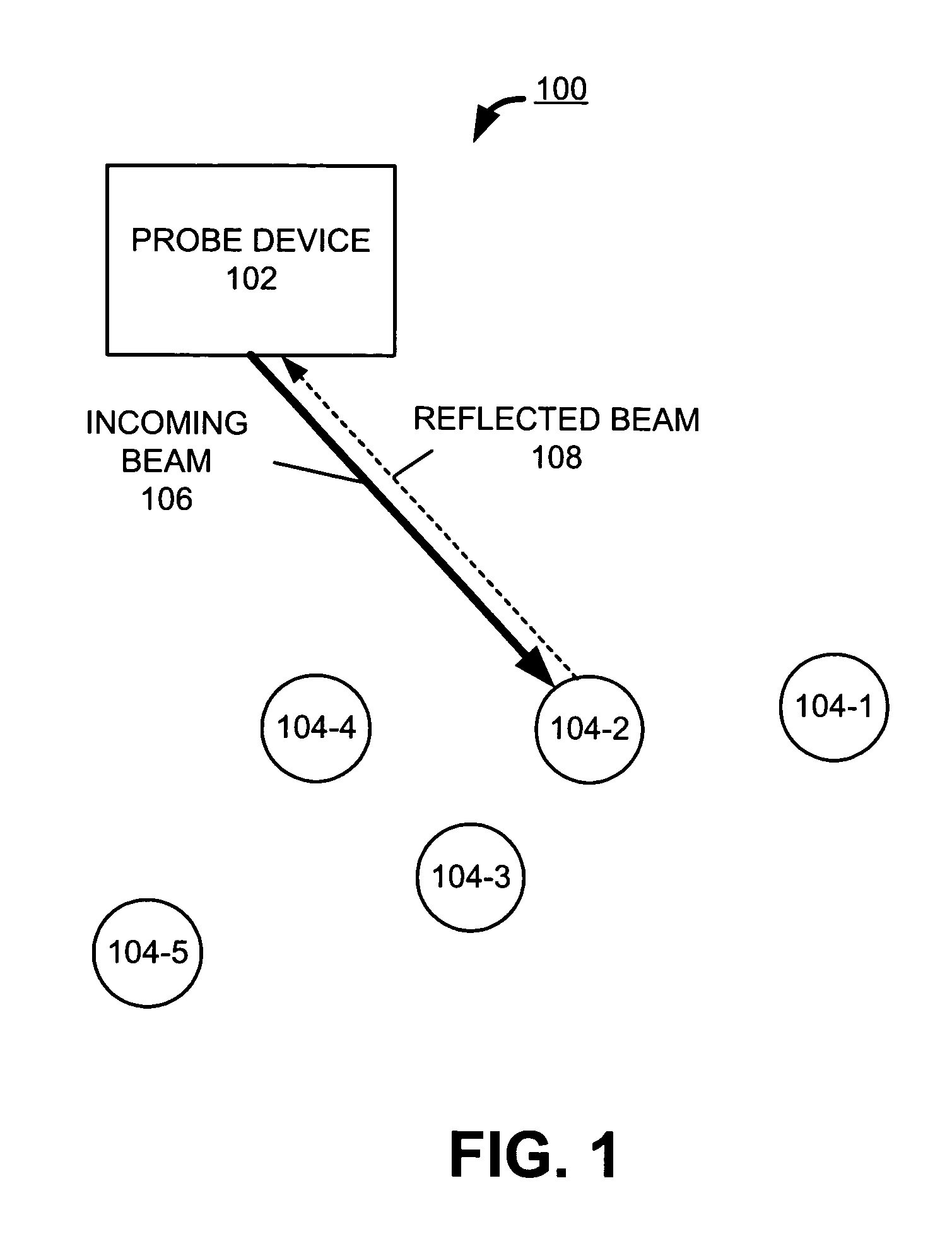
[0017]FIG. 1 illustrates an exemplary system 100 consistent with the principles of the invention. System 100 may include a probe device 102 and a group of retro-reflectors 104-1 to 104-5 (collectively referred to as 104). It will be appreciated that a typical system could include more or fewer devices than are shown in FIG. 1.

[0018]Probe device 102 may include any conventional device capable of transmitting a beam to retro-reflector 104 and receiving a reflected beam from retro-reflector 104. The beam may be implemented by light, radio frequency waves, acoustic waves, or any other mechanism that can act as a carrier and be reflect...


PUM


Abstract

A method, a device and a system for communications to and from a retro-reflector device (302) is provided. The retro-reflector device (302) receives a first frame (400) encoded in an input beam (106). The retro-reflector device (302) creates and sends a second frame (420) in a first reflected beam (108) formed by the retro-reflector device (302) reflecting the input beam (106) along a path closely aligned with a path of the input beam. At least one of the first frame (400) and the second frame (420) includes medium access control information. In some implementations, the first frame (400) may include a data throughput rate (404, 406), a preamble (402) and an error correction code (412).

Description

TECHNICAL FIELD[0001]The invention relates to the field of communications and, more particularly, to systems and methods that send and receive data using modulated retro-reflectors.BACKGROUND OF THE INVENTION[0002]Systems that use modulating retro-reflectors for communications are well-known. One existing system employs modulating retro-reflectors to communicate optically and provides secure, high-speed data communications. However, existing communications systems that employ modulating retro-reflectors do not provide a flexible access control method for controlling communications among a probe device and a group of retro-reflectors, such that each of the retro-reflectors may receive schedule information regarding when respective retro-reflectors may be interrogated for data or may receive data. Further, a need exists for a system that permits a schedule for exchanging data between the probe device and any one of the retro-reflectors to be adjusted based on conditions, such as an am...

Claims


Application Information

Patent Timeline
Patent Type & Authority Patents(United States)
IPC IPC(8): H04B10/00
CPCH04B10/2587
Inventor ELLIOTT, BRIG BARNUM
Owner RAYTHEON BBN TECH CORP
Learn More