Temperature prediction system and method

a technology of temperature prediction and thermometer, applied in the field of electronic predictive thermometers, can solve the problems of affecting the accuracy of the thermometer, the inability to accurately predict the temperature of the body, so as to achieve the effect of reducing the time for data acquisition and data processing

Active Publication Date: 2008-01-08
CAREFUSION 303 INC
View PDF21 Cites 71 Cited by
  • Summary
  • Abstract
  • Description
  • Claims
  • Application Information

AI Technical Summary

Benefits of technology

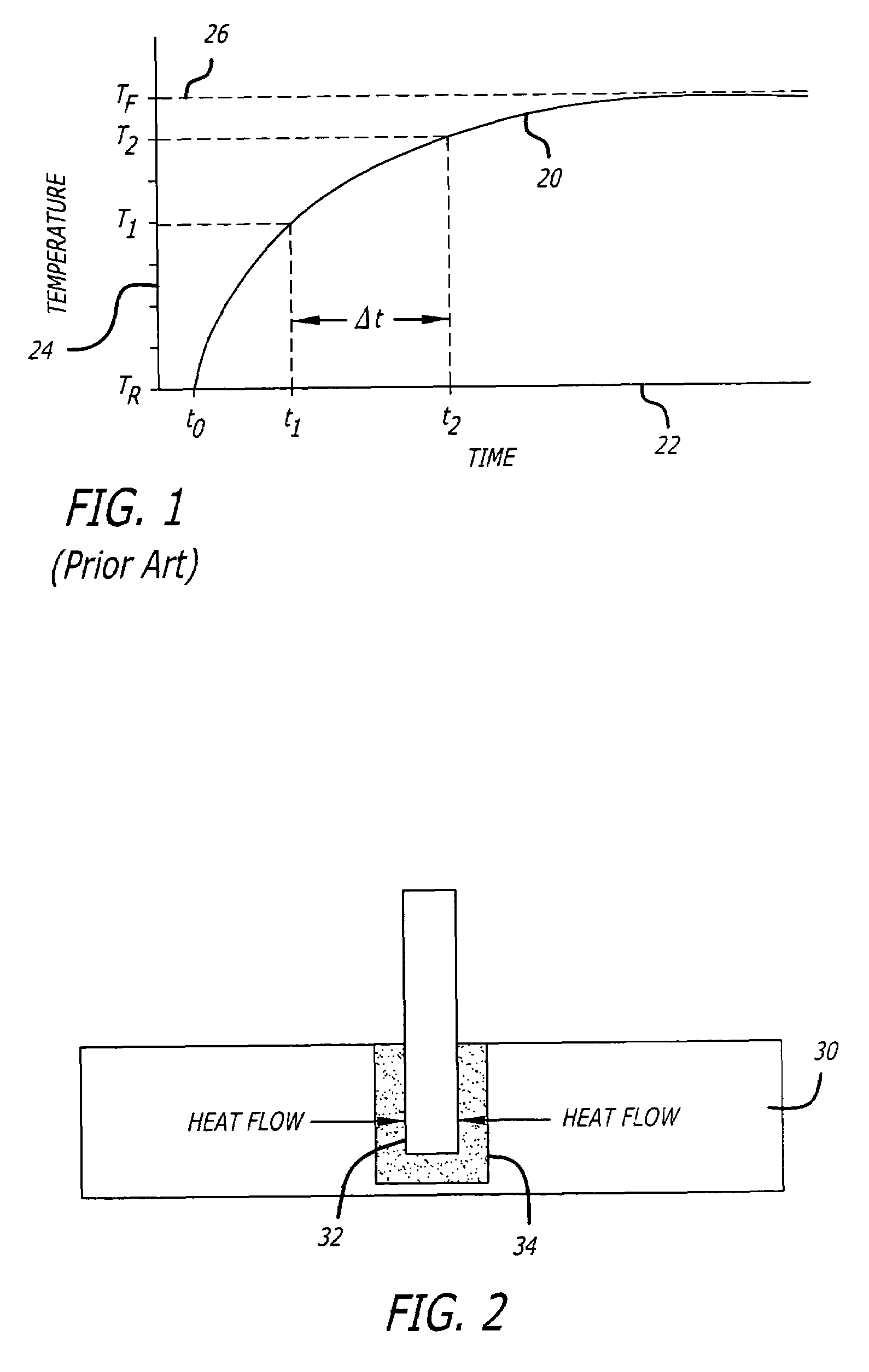
[0036]Briefly and in general terms, the present invention provides a thermometer and method for determining the temperature of a subject by predicting the subject's temperature at an early stage of the measurement process. The thermometer system and method of the present invention adapt a nonlinear model containing multiple parameters to fit a model curve to the monitored temperature data. The parameters are selected at an early portion of the temperature rise curve and from the resulting model curve, the equilibrium temperature of the sensor, and hence the subject, is predicted. In this way, the predictive process is adaptive with respect to the thermal characteristics of the thermometer probe as well as the anatomy and physiology of the subject, and requires relatively little data acquisition and data processing time while yielding accurate predictions of the equilibrium temperature of the sensor.

Problems solved by technology

The conventional temperature measurement procedure using a glass bulb thermometer or the like is prone to a number of significant deficiencies.
Temperature measurement is rather slow and, for patients who cannot be relied upon (by virtue of age or infirmity) to properly retain the thermometer for the necessary period of insertion in the body, may necessitate the physical presence of medical personnel during the relatively long measurement cycle, thus diverting their attention from other duties.
Furthermore, glass bulb thermometers are not as easy to read and, hence, measurements are prone to human error, particularly when made under poor lighting conditions or when read by harried personnel.
This is commonly referred to as the direct reading approach and while it reduces the possibility of error by misreading the measured temperature, it may still require a relatively long period of time in which to reach a stabilized temperature reading.
However, a disadvantage with such a thermometer is that the accuracy with which temperature is predicted declines markedly unless the processing and analysis of the data are accurately performed.
However, all these techniques have failed to recognize that the temperature response curve cannot be accurately modeled as first order since it is determined by the complex thermodynamic interactions of the patient's tissue and vascular system with the hygienic probe cover, sensor, and probe stem.
Application of this simple model to the warming of a temperature probe placed in contact with a portion of the body such as the mouth or the axilla fails to account for the finite heat capacity of the tissues in the immediate region of the probe and for the thermal resistance of the successive layers of tissue beginning with epidermal layer and proceeding to the inner structures.
Practical constraints limit the number of terms that can be employed and thus impose limits of the accuracy of such approaches.
While a thermometer with a much larger processor, with much faster computational speed, with much larger memory size could be made available so that computations could be performed faster and many more computations could be performed, the question of cost arises.
Such increase in processing power would substantially increase the cost of a thermometer and may consequently make it unavailable to many patients.
Various factors may come into play with a particular patient that make one or more of these sites unavailable for use in temperature measurement.

Method used


Image

  • Temperature prediction system and method
  • Temperature prediction system and method
  • Temperature prediction system and method

Examples


Embodiment Construction

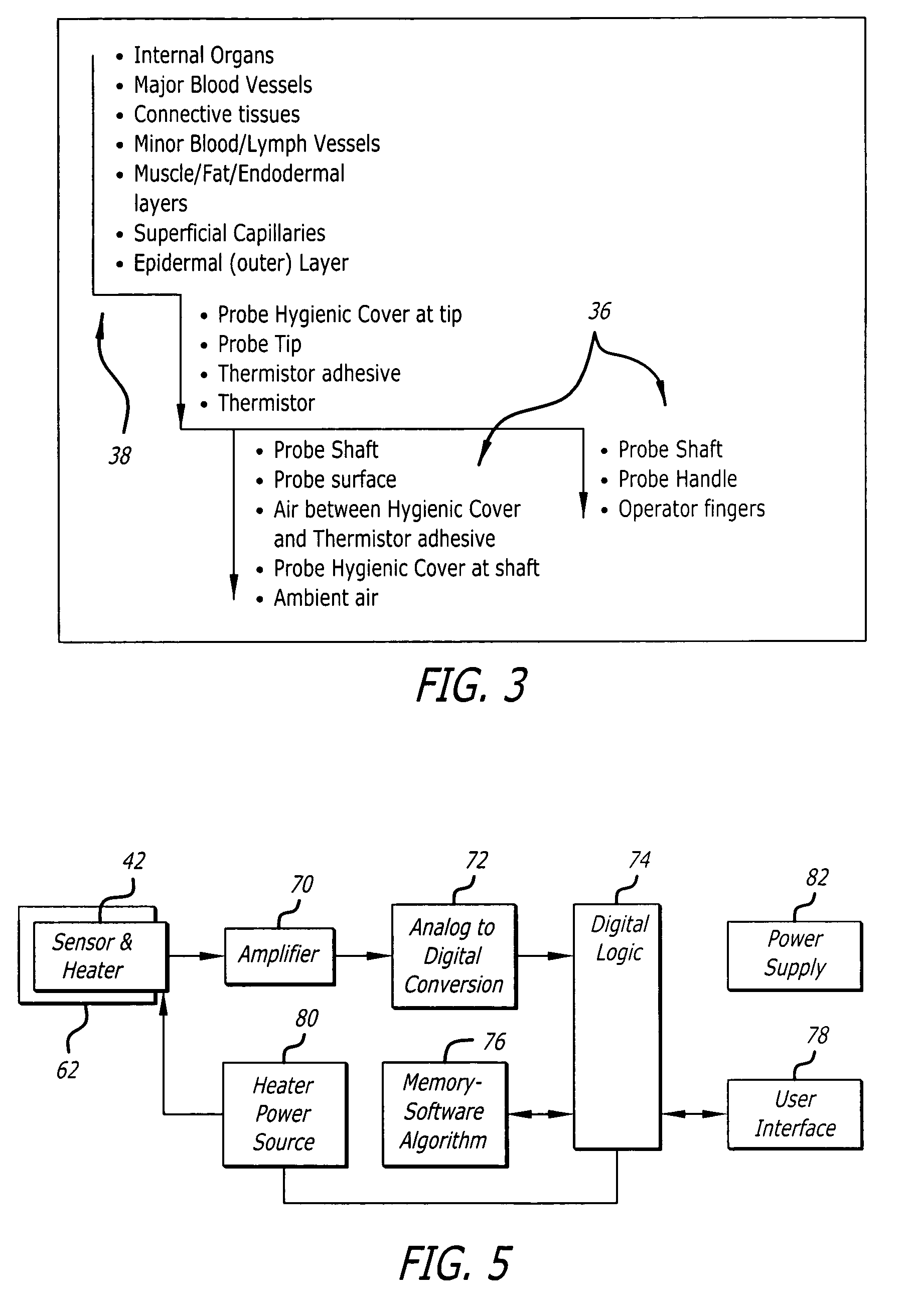
[0057]In the following description, like reference numerals will be used to refer to like or corresponding elements in the different figures of the drawings. Referring now to the drawings, and particularly to FIG. 4, there is shown one embodiment of an electronic thermometer 40 incorporating novel features of the present invention. The electronic thermometer contains a probe 42 for sensing the temperature of a selected part of the patient's body, connected by conductors 44 to the main body 46 of the thermometer. The probe has been removed from a storage well 48 in the main body. The main body of the thermometer contains the electrical components and power supply of the thermometer, and also has a display 50 for displaying temperature values and error or alarm messages, and a first input device 52, which in this case, is an on / off switch located below the display. A MODE switch 54 is also provided at the front panel 56 of the main body to select the site and method of processing the ...


PUM

PropertyMeasurementUnit
contact temperatureaaaaaaaaaa
temperatureaaaaaaaaaa

Abstract

A thermometer system and method that rapidly predict body temperature based on the temperature signals received from a temperature sensing probe when it comes into contact with the body. A nonlinear, multi-parameter curve fitting process is performed and depending on the errors in the curve fit, parameters are changed or a prediction of the temperature is made. Criteria exist for the differences between the curve fit and the temperature data. The processor switches to a Continuous Monitor State if the curve fit over a limited number of time frames is unacceptable. Determining the start time on which the measurement time frame for prediction is based is performed by tissue contact threshold coupled with a prediction time delay.

Description

BACKGROUND[0001]The invention relates generally to improvements in thermometers and, more particularly, to electronic predictive thermometers for more rapidly obtaining accurate temperature measurements from a plurality of patient measurement sites.[0002]It is common practice in the medical arts, as in hospitals and in doctors' offices, to determine the body temperature of a patient by means of a temperature sensitive device that measures the temperature and displays that measured temperature. One such device is a glass bulb thermometer incorporating a heat responsive mercury column that expands and contracts adjacent a calibrated temperature scale. Typically, the glass thermometer is inserted into the patient, allowed to remain for a sufficient time interval to enable the temperature of the thermometer to stabilize at the body temperature of the patient, and subsequently removed for reading by medical personnel. This time interval is usually on the order of two to eight minutes.[00...

Claims


Application Information

Patent Timeline
Patent Type & Authority Patents(United States)
IPC IPC(8): G01K1/00
CPCG01K7/42G01K1/02G01K7/04G01K7/22G01K2219/00G01K13/20
Inventor BUTTERFIELD, ROBERT D.
Owner CAREFUSION 303 INC
Why Eureka
Try Eureka