
Fiber conveying and discarding device to be connected to a carder

a technology of conveying and dumping device and carder, which is applied in the direction of lap winding device, lap forming device, textiles and paper, etc., can solve the problems of carder working speed, draw frame working speed, and carder working speed, etc., to achieve substantial freedom of vibration, low weight, and high strength

Inactive Publication Date: 2008-01-15
ROSINK GMBH & CO KG
View PDF11 Cites 0 Cited by
  • Summary
  • Abstract
  • Description
  • Claims
  • Application Information

AI Technical Summary

Benefits of technology

[0013]Finally, according to the invention, means are provided for changing the drive speed of the can coiler upon signal emission by one of the signal transducers and as a function of the time interval elapsed since the last signal emission. Only when one of the end positions is reached, an adjustment of the basic transmission is realized by intervention in the working speed of the can coiler. The longer the time interval between sequentially reaching the end positions, the smaller the speed adjustment of the can coiler.
[0015]Also advantageous is the calm running of the sliver by guiding the sliver across the spatially displaceable deflection means that can no longer affect the quality of the sliver reached at the time of leaving the draw frame. Especially at the desired high sliver speeds such a sliver guiding action is characterized by a calmer conveying action of the sliver as compared to, for example, a freely sagging loop as disclosed in connection with a continuously operating level sensor in U.S. Pat. No. 5,774,940. An additional disadvantage of a level sensor for detecting a sagging sliver loop resides in that the undefined sagging of the sliver loop can lead precisely to such distortions within the sliver that have been removed prior within the regulating draw frame.
[0016]In accordance with a preferred embodiment of the fiber conveying and depositing device, it is proposed that for detection of the two end positions two signal transducers are provided, respectively, and arranged minimally displaced relative to one another. In this way, an approach of the end position can already be detected signal-technologically and, accordingly, the control can be refined. As signal transducers, proximity switches are preferably used.
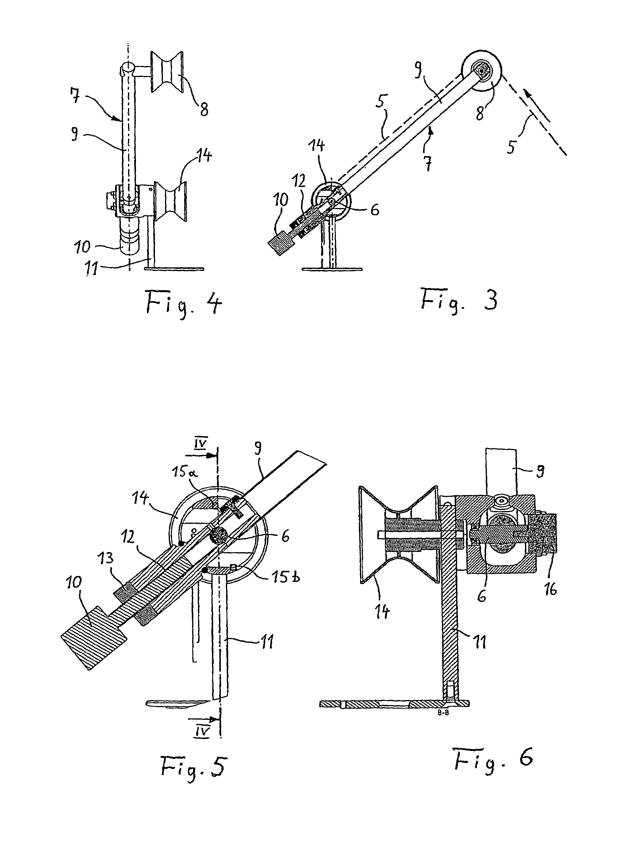
[0018]For the swivel arm an especially light-weight and thus almost inertia-free construction is proposed according to which the arm is comprised of a thin-walled tube. Particularly suitable is a tube of carbon fibers which combines the advantage of minimal weight with high strength and substantial freedom of vibration. Such an arm operates with very minimal inertia moments and therefore has excellent response behavior in regard to any extension or shortening of the sliver deflected about the arm.
[0019]An additional roller that is stationarily supported on the pivot axis for the arm and acts in this case as an additional deflection means also contributes to improving the response behavior of the deflection means relative to any length change of the sliver. Preferably, for this purpose the pivot axis for the arm is arranged above the can coiler and the sliver is vertically guided between the additional roller and the can coiler such that the sliver reaches the can coiler on the shortest possible path and vertically from top to bottom.
[0020]For obtaining an exact response behavior of the deflection means, it is advantageous when the deflection means can be displaced only relative to a certain counterforce, for which purpose preferably a damping mechanism is used. Accordingly, one embodiment of the device is characterized in that the deflection means are provided with a damping element having a progressive damping characteristic line and acting in the displacement direction so that vibrations that are unfavorable for regulating the can coiler are substantially prevented. Preferably, the damping element is arranged such that it acts in a damping fashion on the pivot axis of the swivel arm.

Problems solved by technology

With regard to control technology, the device according to said Swiss letters patent is very complex.
The principal problem resides in that the working speed of the carder on the one hand, of the draw frame on the other hand, and finally of the can coiler must be adjusted relative to one another in a suitable way.
In practice, one is however often faced with the problem of having to mount a can coiler and an interposed draw frame additionally on an already present carder or to retrofit the carder therewith.
In such situations, it is often impossible or possible only with high technical expenditure to intervene in the speed control of the carder in the context of an overall regulation of the system.
The reason for this resides in relatively large moved masses of the can coiler that, in the case of a sudden speed adjustments, cause high mechanical forces particularly on the bearing of the rotating head of the can coiler.

Method used


Image

  • Fiber conveying and discarding device to be connected to a carder
  • Fiber conveying and discarding device to be connected to a carder
  • Fiber conveying and discarding device to be connected to a carder

Examples


Embodiment Construction

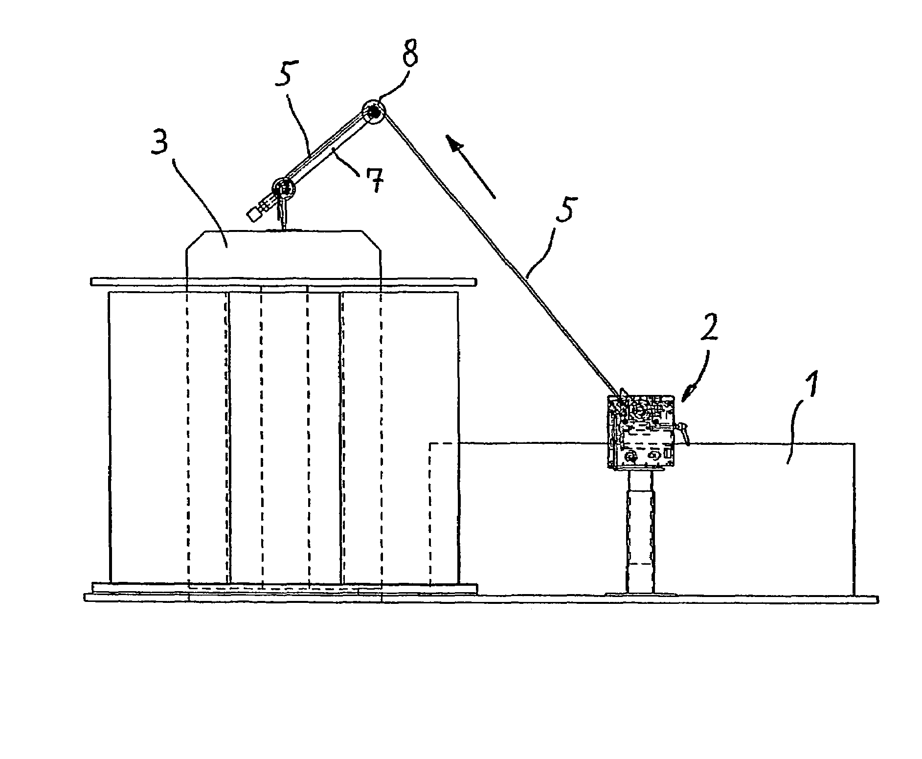
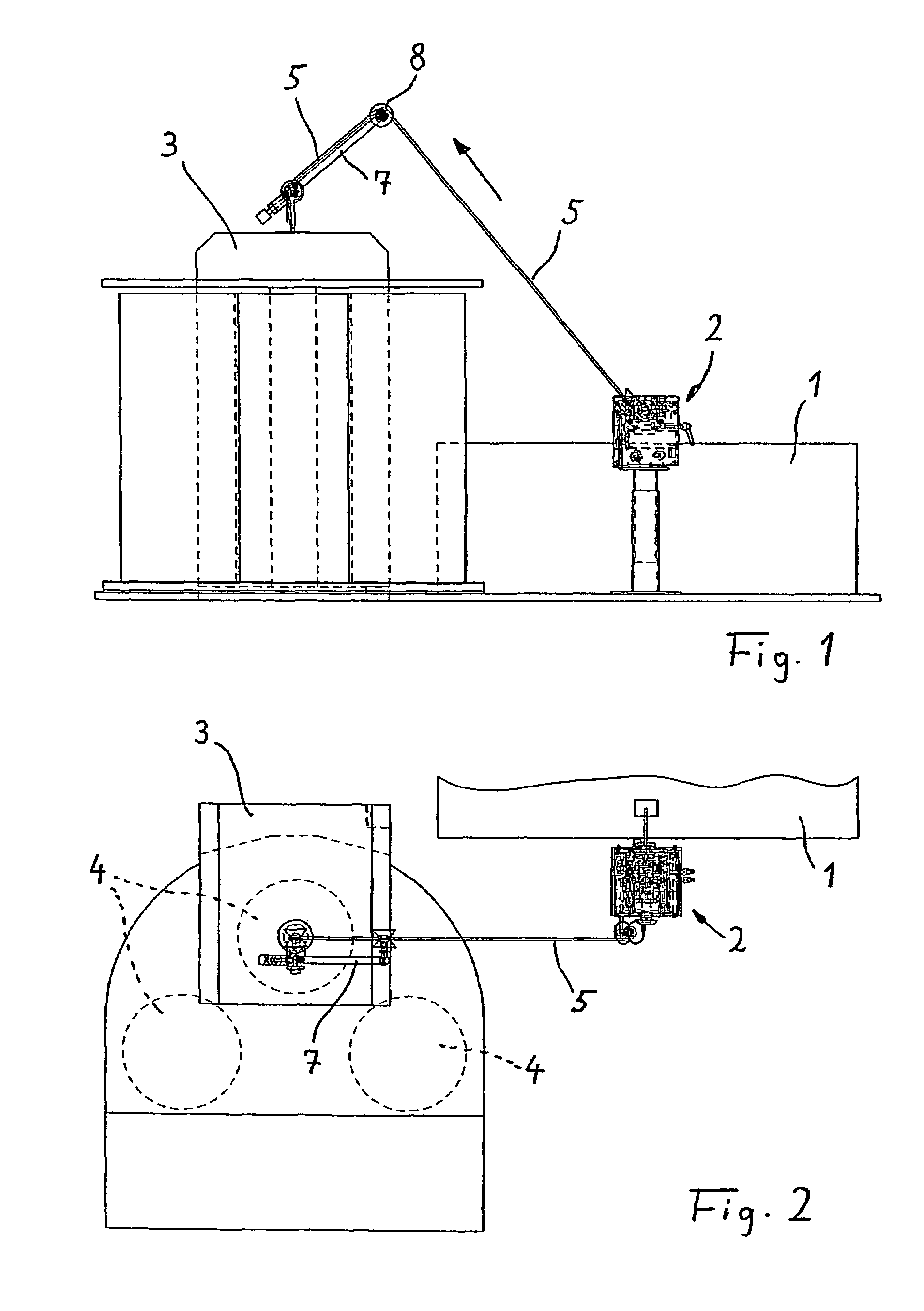
[0028]FIGS. 1 and 2 show in an overall illustration a carder 1, only partially illustrated, that has arranged downstream thereof a draw frame 2 relative to the sliver conveying direction; downstream of the draw frame a can coiler 3 is arranged. In the can coiler 3, a can is deposited, as is known in the art, into which can the sliver is placed in loops in a controlled fashion. In the present case, the can coiler 3 is provided with a can changer which provides space for a total of three sliver cans 4. The sliver is identified by reference character 5.

[0029]A controlled drawing of the sliver coming from the carder 1 is realized in the draw frame 2 in order to improve in this way the structure and in particular the uniformness of the sliver. Such draw frames are also known, for example, as disclosed in Swiss letters patent CH 692 349. A draw frame is often comprised of several roller pairs wherein at least the last roller pair is driven at a higher individually controllable speed. This...


PUM

PropertyMeasurementUnit
deflection angleaaaaaaaaaa
tensionaaaaaaaaaa

Abstract

In a sliver conveying and depositing device, the sliver is guided from the carder through a draw frame to a can coiler. A first deflection device mounted on the free end of a pivotable arm is arranged between the last driven roller pair of the draw frame and the can coiler. The sliver is guided across the first deflection device and the arm exerts a counter pressure onto the sliver for maintaining sliver tension. The first deflection device is displaceable for compensating the sliver length between first and second end positions, wherein signal transducers emit a signal when the first or second positions are reached. The speed of the can coiler drive is changed when a signal is received from the signal transducers, wherein a time interval elapsed since the last signal has been received from one of the signal transducers is taken into account for changing the speed.

Description

BACKGROUND OF THE INVENTION[0001]The invention relates to a fiber conveying and depositing device to be connected to a carder, wherein a sliver, downstream of the carder exit, passes through a draw frame comprised of at least two driven roller pairs and then reaches a can coiler, wherein the draw frame has a main drive as well as a regulating drive for the last roller pair.[0002]Such a device is disclosed, for example, in letters patent CH 692 349. The sliver leaving the carder reaches first a draw frame and subsequently a can coiler that places the sliver in the form of loops into the can. The draw frame is configured as a regulating draw frame and arranged immediately on top of the can coiler. In this way, it is possible to keep the distance between the exit of the regulating draw frame and the sliver entry opening of the can coiler at a minimum; according to letters patent CH 692 349, this is underscored as being especially advantageous.[0003]With regard to control technology, th...

Claims


Application Information

Patent Timeline
Patent Type & Authority Patents(United States)
IPC IPC(8): D01G25/00D01G23/06
CPCD01G23/06
Inventor STENTENBACH, UDO
Owner ROSINK GMBH & CO KG
Learn More