Deck mounted device with gasket

a technology for gaskets and devices, which is applied in the field of deck mounted devices having a recess and a gasket, which can solve the problems of affecting the sealing of the stud, and affecting the sealing of the washer, so as to prevent water intrusion through the deck of the vessel

Inactive Publication Date: 2008-01-15
AMY RON
View PDF7 Cites 10 Cited by
  • Summary
  • Abstract
  • Description
  • Claims
  • Application Information

AI Technical Summary

Benefits of technology

[0013]The present invention is mechanical configuration providing a method and apparatus for deck mounted devices for vessels, such devices including rope cleats, antenna mounts, fill caps, and the like. A primary object of the invention is to provide a deck mounted apparatus, and means for securing such an apparatus, so as to create a water tight seal that prevents water intrusion through the deck of a vessel.

Problems solved by technology

Unfortunately, tightening the nut forces the flat underside of the support structure onto the surface of the deck, causing caulking material to be squeezed out or any rubber washer to be severely distorted, compromising its seal around the stud.
Additionally, the marine environment includes dramatic temperature swings, humidity changes, corrosive salt water and air, all of which can cause caulking and rubber washers to deteriorate, thus creating a pathway for water to travel and eliminating the protective cushion provided, which may result in damage to the deck caused by the device itself.
The resulting water damage may create the need for expensive and time consuming repairs.
Moreover, if the cleat support structures are resting on a compressible gasket material such as rubber or the like, unwanted movement occurs from side loads when dock lines pull on the cleat.
A further disadvantage in using a compressible gasket is in the increase of flex loads on the threaded stud fasteners and attached nuts.
This may result in mechanical failure causing the cleat to break away from the deck and the moored boat to drift away from its mooring.

Method used


Image

  • Deck mounted device with gasket
  • Deck mounted device with gasket
  • Deck mounted device with gasket

Examples


Embodiment Construction

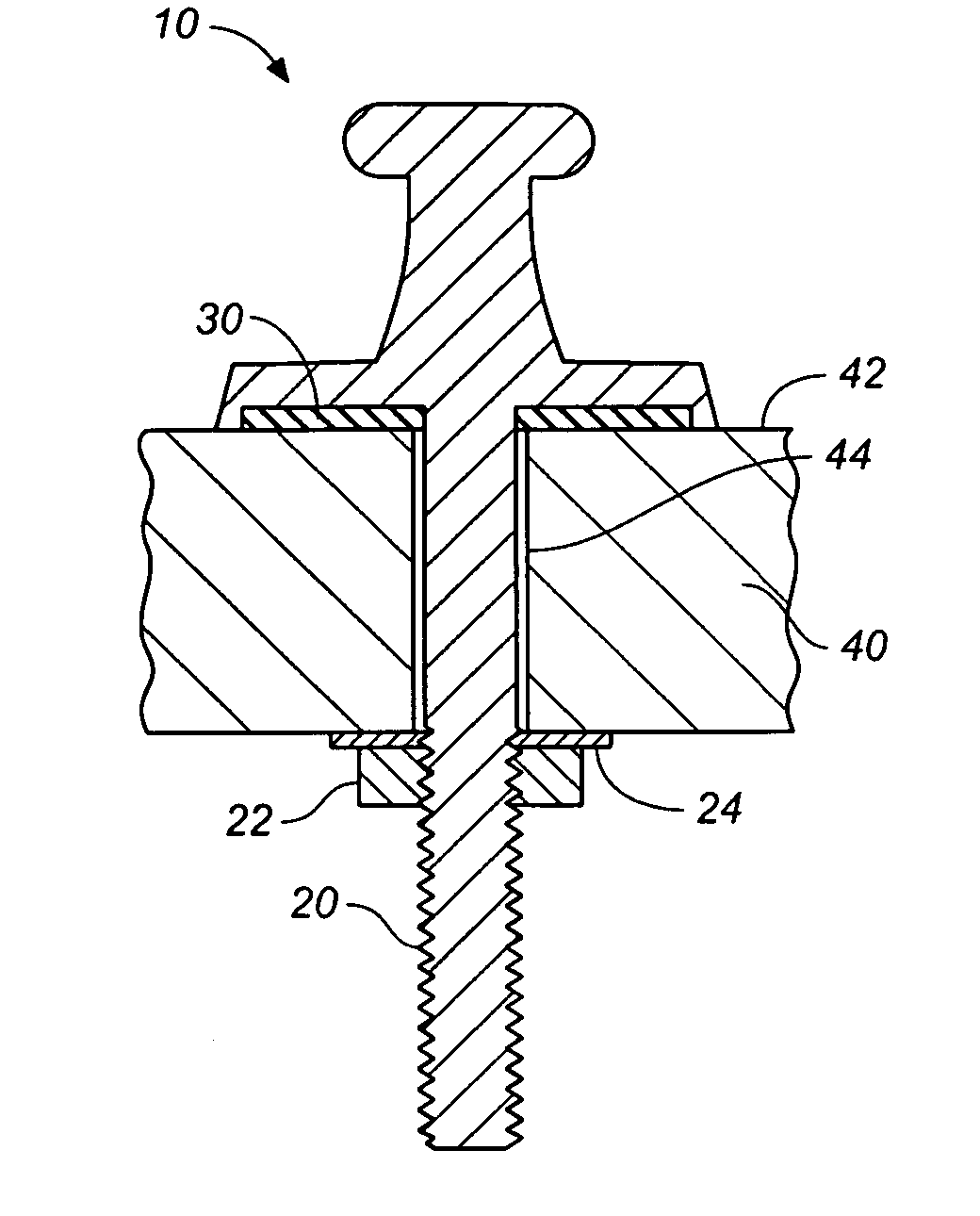
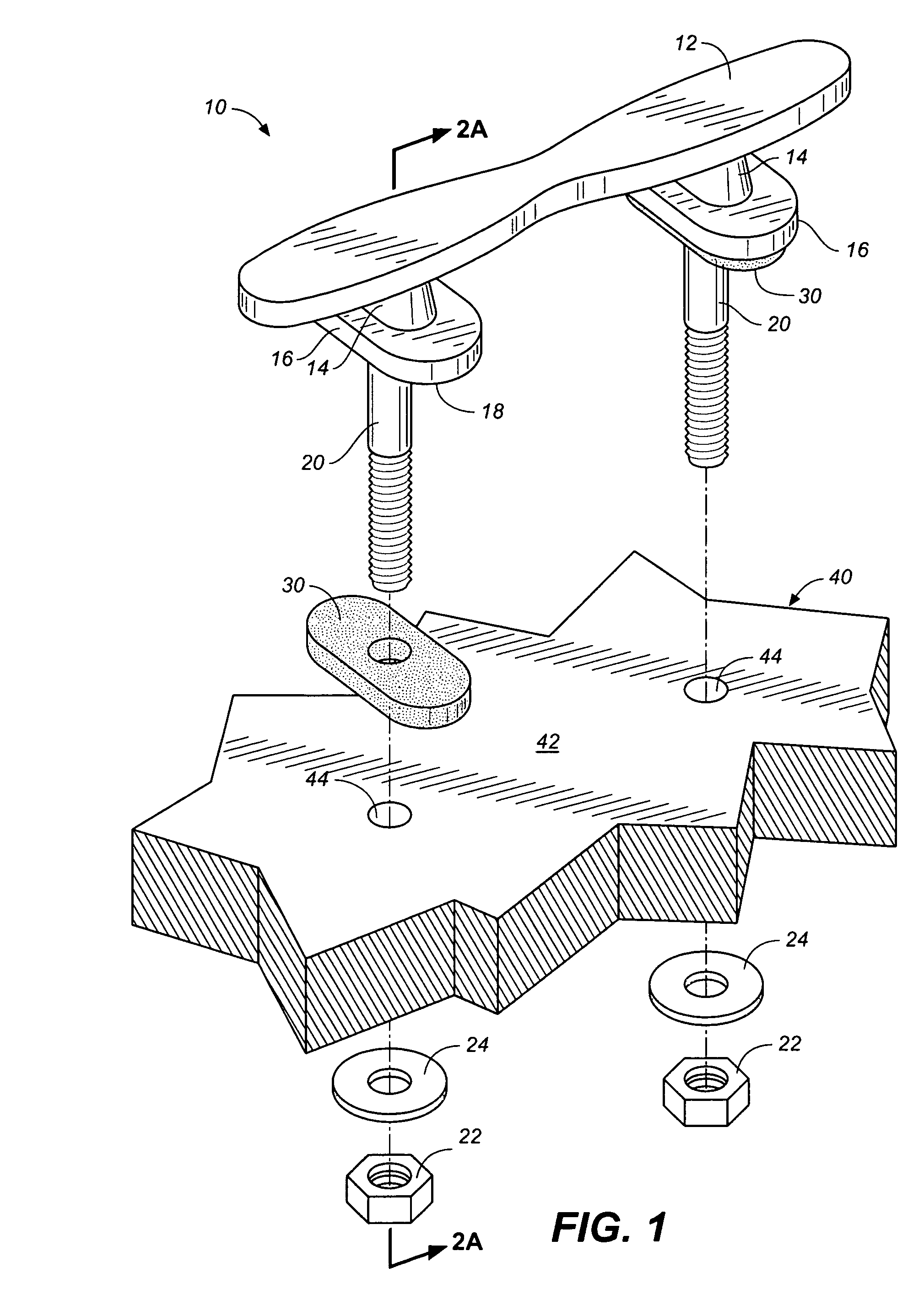
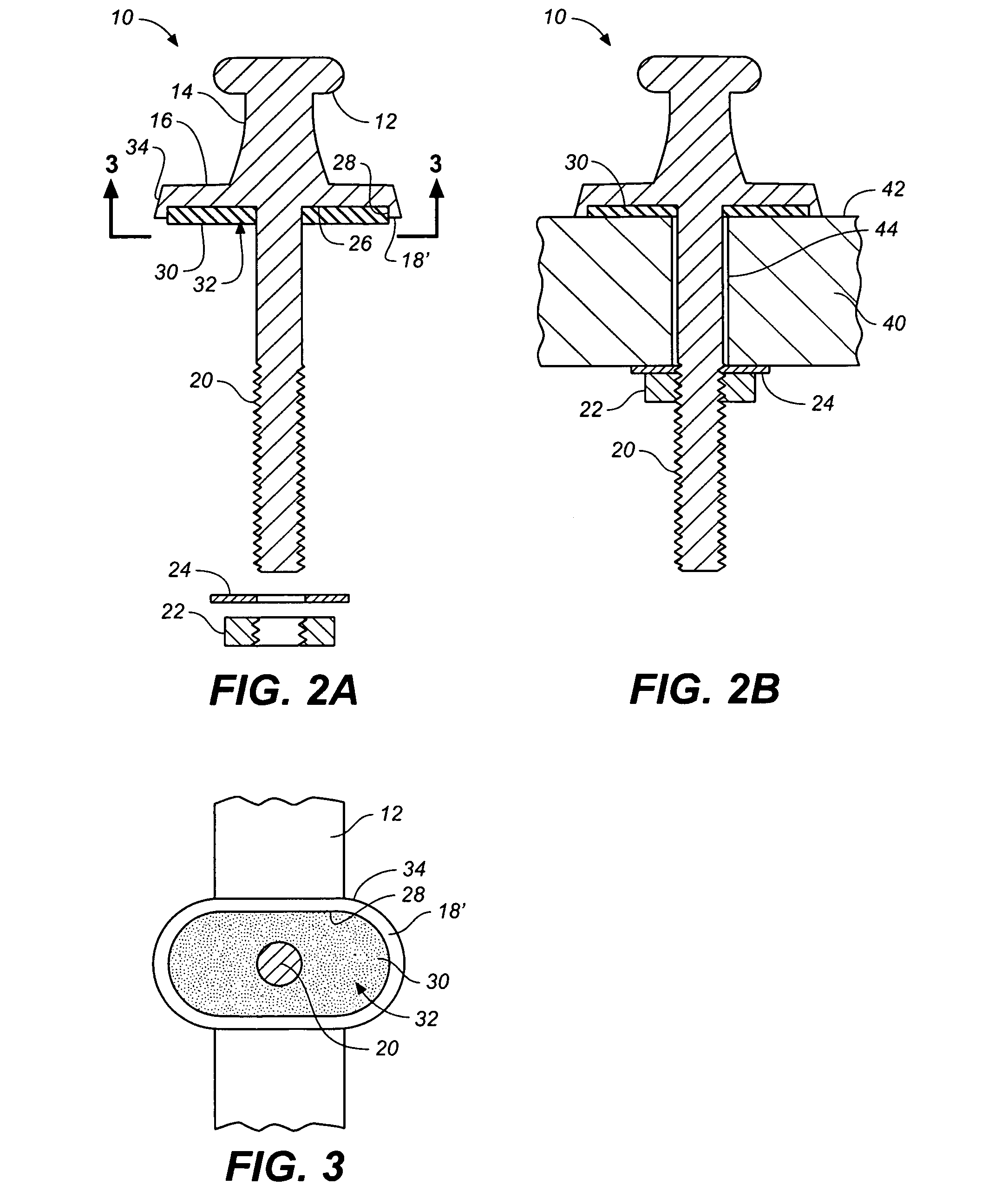
[0029]Referring to FIGS. 1 through 8, wherein like reference numerals refer to like components in the various views, there is illustrated therein a new and improved deck-mounted device having a gasket, the first embodiment of which is generally denominated 10 herein.

[0030]Referring now to FIGS. 1 through 3 we see the first preferred embodiment of the inventive apparatus, namely a cleat 10, positioned for installation on a vessel deck 40. The process and mechanical characteristics detailed in this embodiment may be applied to alternate hardware and hardware elements, as discussed in detail below.

[0031]Cleat 10 is comprised of an elongate rigid bar 12 with a plurality of stand-offs 14. The distal end of each standoff 14 is enlarged to form a base 16. The base 16 has a generally planar underside 18 to conform to a mounting surface 42, which is also typically flat, or generally so. However, the underside could be shaped to conform to any non-flat surface.

[0032]Depending downwardly from ...


PUM


Abstract

A deck mounted for installation on the surface of a vessel deck having one or more bolt holes. The apparatus includes one or more base portions, each having a recess region defined by a perimeter wall bounding the perimeter of the base portion. The perimeter walls each have an underside rim. One or more threaded members are provided for insertion through the bolt holes in the vessel deck, and complementary threaded female members are provided, one each to receive and tighten onto a threaded rod. A resilient gasket is disposed in the recess region within the confines of the perimeter wall. The threaded rod passes through the gasket hole, such that when the threaded rods are inserted through the vessel deck, and received by and tightened into the respective threaded female members, the gaskets are displaced and deformed so as to protrude between the underside rims of the perimeter walls and the upper surface of the vessel deck.

Description

CROSS REFERENCES TO RELATED APPLICATIONS[0001]The present application is a continuation-in-part of U.S. Utility patent application Ser. No. 10 / 689,377, filed Oct. 20, 2003 now U.S. Pat. No. 7,032,528.STATEMENT REGARDING FEDERALLY SPONSORED RESEARCH OR DEVELOPMENT[0002]Not applicable.THE NAMES OR PARTIES TO A JOINT RESEARCH AGREEMENT[0003]Not applicable.INCORPORATION-BY-REFERENCE OF MATERIAL SUBMITTED ON A COMPACT DISC[0004]Not applicable.BACKGROUND OF THE INVENTION[0005]1. Field of the Invention[0006]The present invention relates generally to devices mounted to a vessel deck, and more particularly to deck mounted devices having a recess and a gasket disposed in the recess.[0007]2. Discussion of Related Art Including Information Disclosed Under 37 CFR §§1.97, 1.98[0008]Sailing vessels and power boats must be restrained from drifting away from a dock or mooring when stationed in port. To secure the vessel, rope cleats are mounted around the perimeter of the vessel deck so that a rope ...

Claims


Application Information

Patent Timeline
Patent Type & Authority Patents(United States)
IPC IPC(8): B63B21/04
CPCB63B21/04
Inventor AMY, RON
Owner AMY RON
Why Eureka
Try Eureka