
Alpine ski binding heel unit

Active Publication Date: 2008-01-15
KNEEBINDING
View PDF8 Cites 5 Cited by
  • Summary
  • Abstract
  • Description
  • Claims
  • Application Information

AI Technical Summary

Benefits of technology

[0019]Analytically, the lateral heel release includes an incremental lever arm that resists lateral motion. The incremental lever arm is defined by the distance between the point of contact between the tension shaft and the point of contact on the lateral release cam. The incremental lateral release cam tilts during initial and latter phases of release. The lateral release cam tilt allows the instant lateral center of effort (from the longitudinal pressure) of the boot to shift laterally to a point that is farther away from the concentrated point of contact. The rolling nature of the contact interface, defined by the lateral release cam and the matched cam interface, minimizes changes in the coefficient of friction within the cam interface of the lateral heel release mechanism.
[0021]In one or more embodiments, a vector decoupler mechanism separates and isolates undesired release conditions from intended release conditions. The vector decoupler mechanism filters events including induced roll loads (due to edging on snow or ice), forward bending moments, vertical forces and backward bending moments from the primary lateral and vertical heel release mechanisms. The vector decoupler prevents influence on objects including the lateral heel release, the vertical heel release and the longitudinal pressure compensator.
[0026]The design largely blocks the introduction of foreign matter into the lateral heel release cam mechanism, thereby not significantly affecting performance. The open space between the lateral release cam and the matching cam interface may be partially filled with a compressible rubber-like polymer to prevent the introduction of mud, road-salt and ice contaminates.

Problems solved by technology

Vertical heel release bindings have serious disadvantages because vertical release bindings only release the ski when there is downward stress imparted by the skier on the ski where the area of applied stress is located in front of the boot's fulcrum point, which fulcrum is typically located under the ball of the foot; or release the ski when there is an upward stress applied to the ski by the skier when the skier is turned backwards in a fall with the top / aft section of the ski being dragged in the snow.
Accordingly, with heels that only provide vertical release, lateral release of the ski from the boot is not possible when lateral forces are applied to the ski immediately under or near the heel that only releases vertically.
A heel that releases in the vertical direction only which relies on a lateral releasing toe can be dangerous to the knee in the event of lateral forces being applied to the ski immediately under a heel that only provides vertical release, because a lateral force applied to a non-releasing ski, under a non-lateral releasing heel, can act over the entire length of the lower leg to generate a moment about the femur when the knee is bent at nearly 70-degrees to 110-degrees, which femur is semi-rigidly attached to the hip, thereby producing very high strain across the anterior cruciate ligament of the knee, often causing rupture of the ACL
These heel unit bindings, however, have serious disadvantages.
These disadvantages include unsatisfactory lateral and vertical retention of the ski to the boot.
Multi-directional release bindings that exhibit unsatisfactory lateral and vertical ski retention fail to retain skis to boots during normal controlled skiing which gives rise to a condition called pre-release.
However, the increase in retention also increases the release level, negating the original benefits that multi-directional bindings are intended to resolve.
Many of the multi-directional heel release bindings have offered the promise of improved release but have failed to provide adequate retention in practice.
Consequently, previous multi-directional heel bindings do not meet fundamental design requirements of an alpine ski binding including providing proper retention of a ski to a boot during controlled skiing maneuvers
There is also one multi-directional heel unit which provides false-positive retention, because it provides retention during controlled skiing, but fails to allow proper lateral heel release when roll moments (from edging) are induced into the binding, and is being taken to market, regardless, because there is no international standard that tests for the effects of induced roll moments on proper lateral heel release.
Despite improvements in multi-directional toe release bindings, the incidence of knee injuries continues to increase.
However, center release mechanisms show evidence of internal friction, especially during induced roll moments from edging.
The presence of snow and ice melts deposits large amounts of dirt and grit in the release interfaces.
The deposition greatly increases the resultant twist release and subsequent resultant torsional loading induced into the tibia during combined forward twisting falls, by as much as 300%, easily causing a fractured tibia.

Method used


Image

  • Alpine ski binding heel unit
  • Alpine ski binding heel unit
  • Alpine ski binding heel unit

Examples


Embodiment Construction

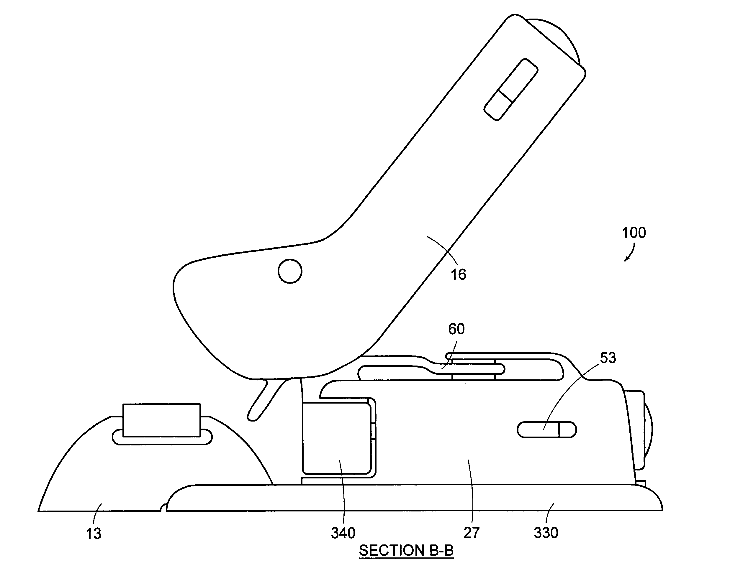
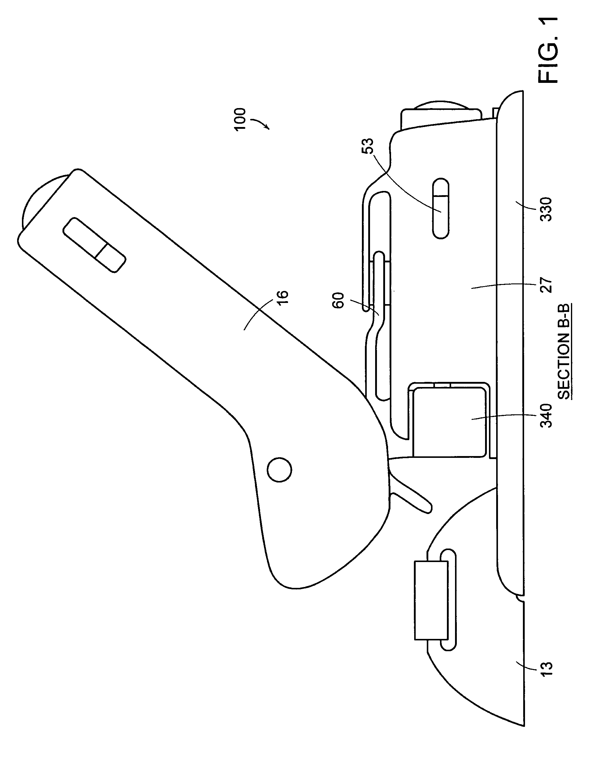
[0032]FIG. 1 shows a sectional side view of a ski binding heel unit 100. The ski binding heel unit includes an upper heel housing 16, lower heel housing 27, heel pad 13, lateral release 340, interface support 330, and vector decoupler mechanism 60. Heel pad 13 connects to interface support. The heel housing is disposed on the lateral release 340, which is connected to the vector decoupler mechanism 60.

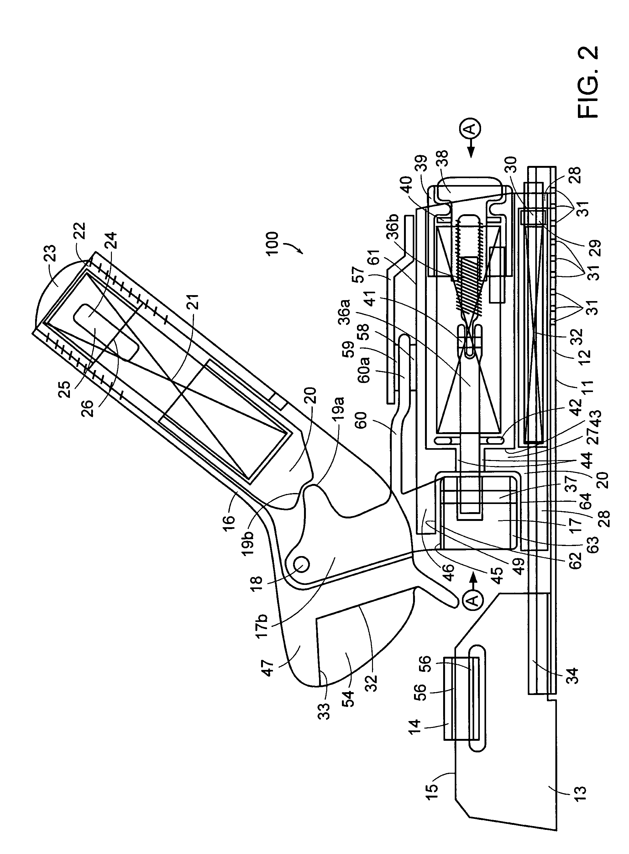
[0033]FIG. 2 details a side view of the alpine ski binding heel unit shown in FIG. 1. Upper Heel housing 16 includes a pivot rod 18, cam surfaces 19a and 19b stem section 17b, lateral release cam assembly 17, vertical release cam follower 20, vertical release spring 21, threaded cap 22, window 24, polymer piece 25, surface 26, region 33, and heel cup assembly 47.

[0034]As used herein, the longitudinal and horizontal plane of the ski is that plane which is parallel to the bottom surface of the ski. The longitudinal and vertical plane of the ski is that plane which is perpendicular to the...


PUM


Abstract

Ski binding heel unit includes lateral release cams and a vector decoupler mechanism that provide lateral shear release of the heel of a ski boot from a ski. The ski binding heel unit includes an independent vertical heel release mechanism, independent lateral release mechanism and a forward pressure compensator. The lateral release cams have laterally outwardly flaring contact points. The vector decoupler mechanism restricts heel unit lateral rotation and translation to a control path. The shape of the lateral release cams dictates the control path. The vector decoupler mechanism redirects the non-lateral forces without effecting the vertical heel release, lateral heel release or forward pressure compensator. The lateral release cams and vector decoupler mechanism avert non-lateral, benign loads from the lateral heel release, and avert non-vertical, benign loads from the vertical heel release thereby reducing the incidence of inadvertent pre-release of a boot from a ski.

Description

CROSS-REFERENCE TO RELATED APPLICATIONS[0001]This application claims priority to U.S. Provisional Appl. Ser. No. 60 / 448,645, filed on Feb. 18, 2003, entitled ALPINE SKI BINDING HEEL UNIT, under 35 U.S.C. §119(e) which is expressly incorporated herein by reference in its entirety.BACKGROUND[0002]This invention relates in general to alpine ski bindings and, in particular, to multi-directional release alpine ski binding heel units that release in the vertical and lateral directions.[0003]Ski binding heel units have a jaw that is adapted to hold a boot and move between a boot retention position and a release position. The jaw vertical pivots around an axis transverse to the longitudinal axis of the ski and / or binding against the action of an elastic system. The elastic system comprises a mobile member biased by a spring against a release incline on a support attached to the ski. Vertical heel release bindings have serious disadvantages because vertical release bindings only release the ...

Claims


Application Information

Patent Timeline
IPC IPC(8): A63C9/084A63C9/00A63C9/085
CPCA63C9/001A63C9/0846A63C9/0845A63C9/0844
Inventor HOWELL, RICHARD J.
Owner KNEEBINDING
Learn More