Differential anti-pinch capacitive sensor

a capacitive sensor and anti-pinch technology, applied in the field of proximity sensors, can solve the problem of becoming relatively more difficult to sense small objects near the electrod

Inactive Publication Date: 2008-01-15
INTIER AUTOMATIVE CLOSURES INC
View PDF14 Cites 34 Cited by
  • Summary
  • Abstract
  • Description
  • Claims
  • Application Information

AI Technical Summary

Problems solved by technology

One of the problems with the known prior art capacitive sensing systems relates to the distance between the electrode(s) and the sheet metal or chassis ground of the automobile, which is in relative close proximity to the sensor electrode(s).
Accordingly, it becomes relatively more difficult to sense small objects near the electrode because of the dominance of the background capacitance, and special measures have to be taken to filter out or eliminate this capacitance from the decision-making process.

Method used


Image

  • Differential anti-pinch capacitive sensor
  • Differential anti-pinch capacitive sensor
  • Differential anti-pinch capacitive sensor

Examples


Embodiment Construction

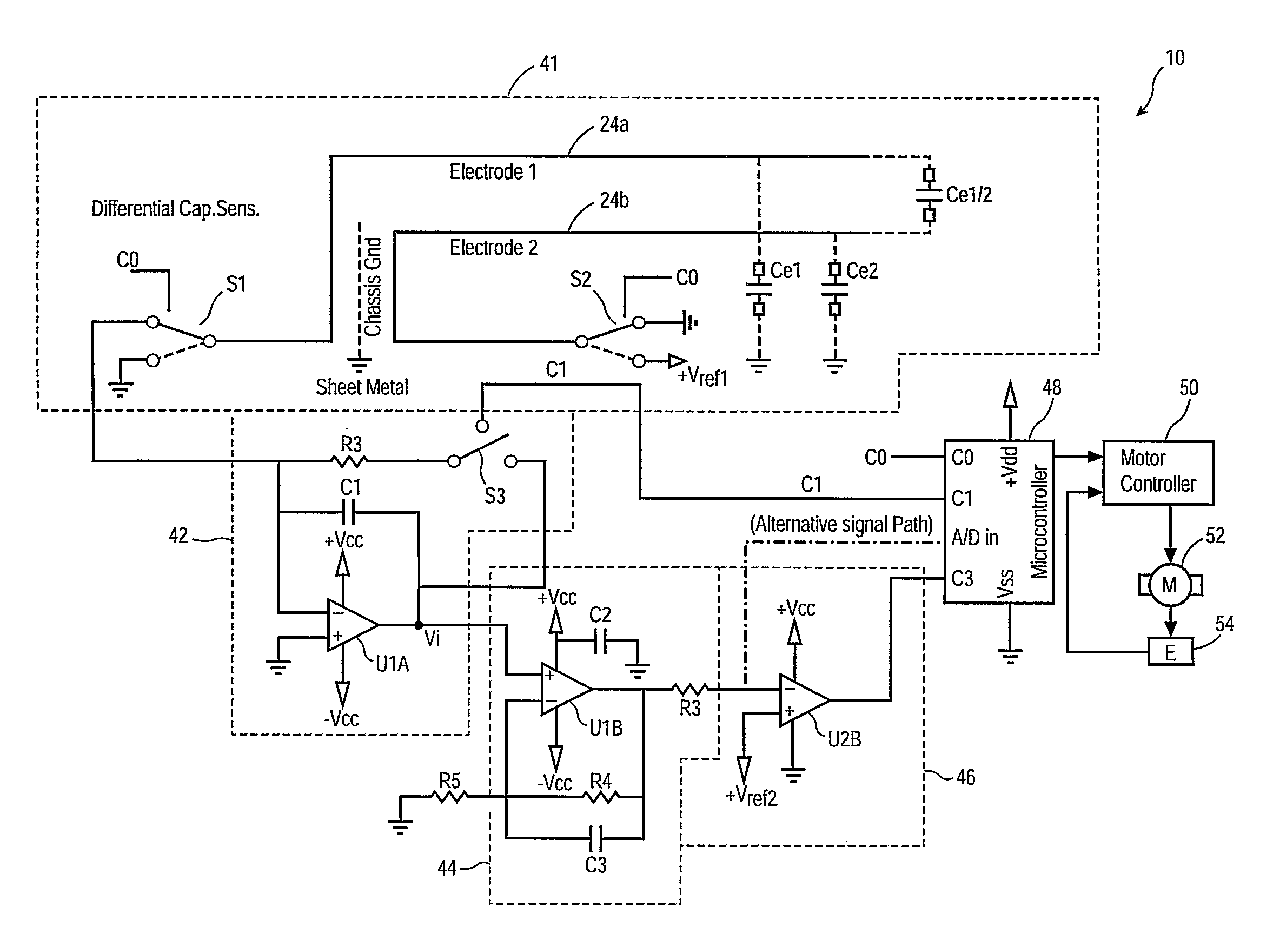
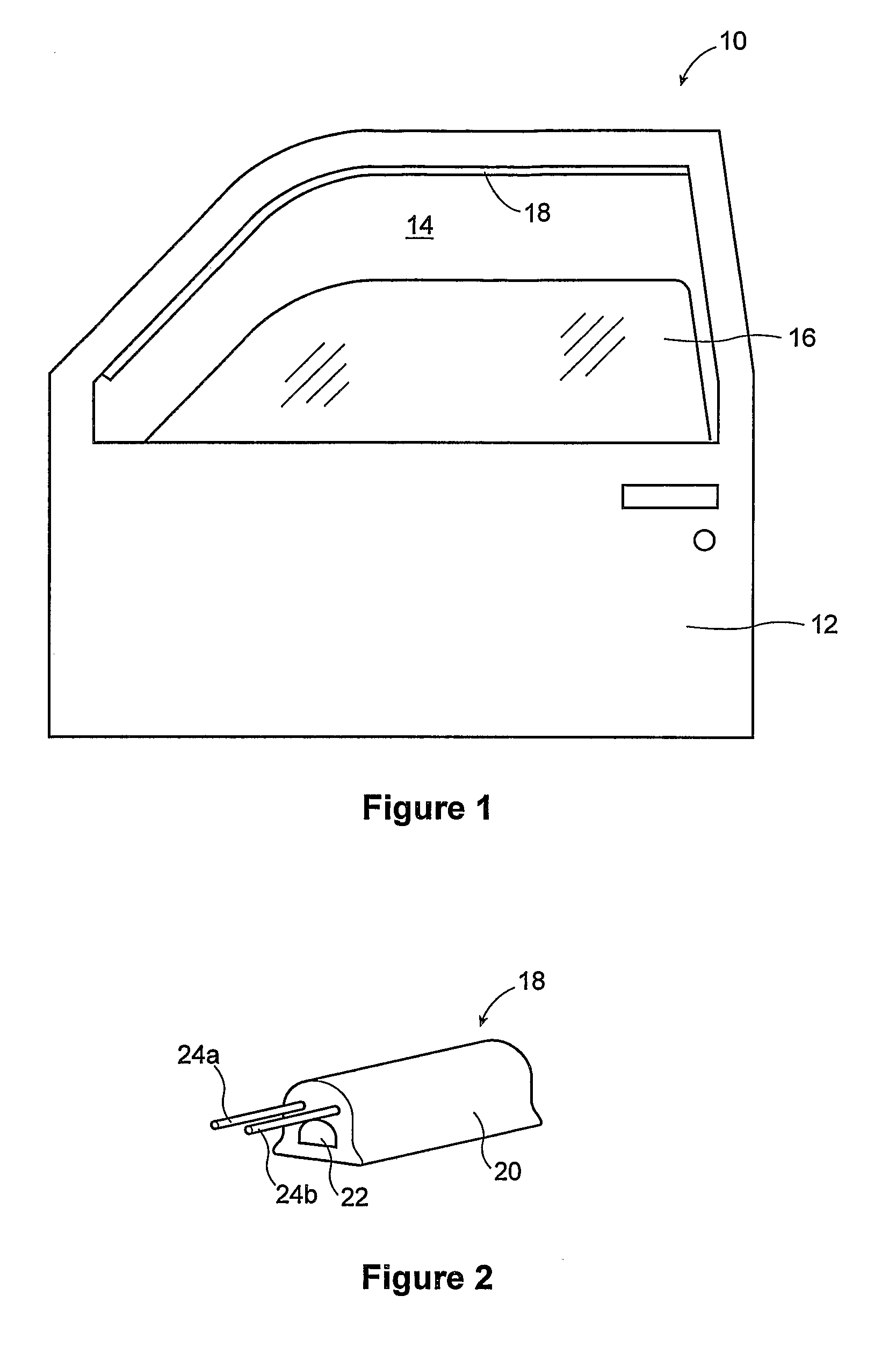
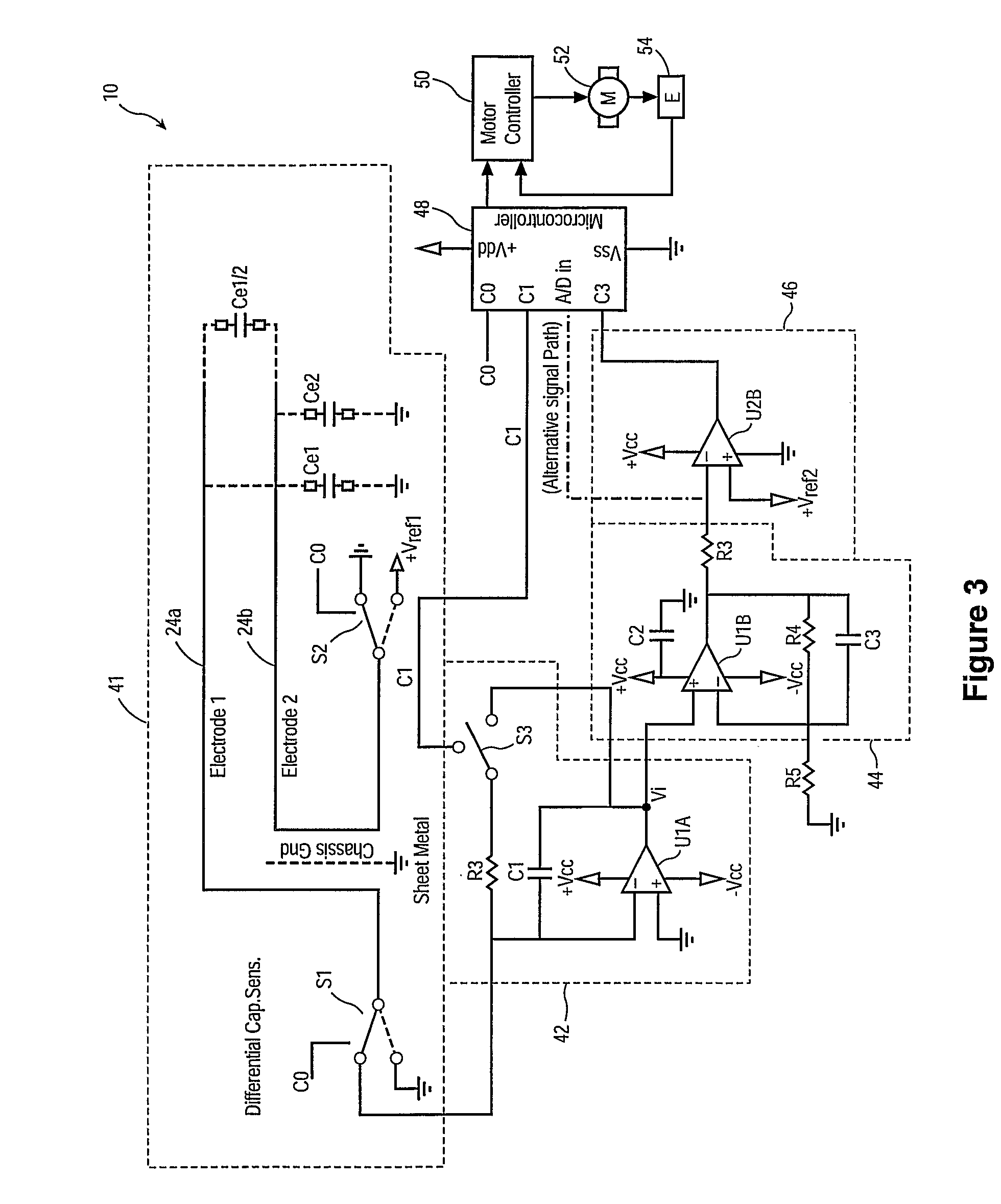
[0017]FIG. 1 illustrates a typical automotive door 12 that is comprised of sheet metal and includes an aperture 14, structured as a window frame 40, which may be closed by a window pane or glass panel 16. The glass panel 16 is raised or lowered by a window regulator (not shown) which includes an electric motor 52 (see FIG. 3) as the motive driving source, as well known in the art, per se. The motor 52 is controlled in part by a non-contact obstruction sensor or anti-pinch assembly 10, the particulars of which are described in greater detail below. The anti-pinch assembly 10 prevents the glass panel 16 from pinching or crushing a foreign object such as a finger (not shown) that may be extending through the aperture 14 when the panel nears its closed position. It will be appreciated by those skilled in the art that the anti-pinch assembly 10 can be applied to any motorized or automated closure panel structure that moves between an open position and a closed position. For example, a no...


PUM

PropertyMeasurementUnit
capacitance CE1/2aaaaaaaaaa
capacitance CE1aaaaaaaaaa
voltageaaaaaaaaaa

Abstract

A proximity sensor for sensing an object in the path of or proximate to a closure panel such as a vehicle window. First and second electrodes encased in a non-conductive casing are mounted on the metallic structure near the closing edge of the aperture. The two electrodes define a capacitance CE1 / 2 therebetween, and parasitic capacitances CE1 and CE2 between the first electrode and chassis ground and the second electrode and chassis ground, respectively. A controller cyclically connects (1) the second electrode to a voltage reference source (Vref1) and the first electrode to chassis ground and (2) the second electrode to chassis ground and the first electrode to the reference capacitor, thereby periodically charging the capacitance CE1 / 2 and transferring the charge stored thereon to the reference capacitor whilst short-circuiting the parasitic capacitances. The charge on the reference capacitor, the time period required to charge the reference capacitor to a specified voltage, or a calculated value for CE1 / 2 are then compared against a reference value in order to derive an obstruction signal.

Description

BACKGROUND OF THE INVENTION[0001]1. Field of the Invention[0002]The present invention relates to a proximity sensor. In particular, the invention relates to a non-contact strip sensor for identifying the presence of proximate objects from variations in an electric field.[0003]2. Description of the Related Art[0004]Proximity sensors are widely used in the automotive industry to automate the control of power accessories. For instance, proximity sensors are often used in power window controllers to detect the presence of obstructions in the window frame when a window panel is being directed to the closed position. Such sensors can also be used to detect the presence of obstructions in other types of automotive closures such as sunroofs, side doors, sliding doors, lift gates, and deck lids.[0005]A variety of capacitor-based proximity sensors are known in the art. For example, U.S. Pat. No. 6,377,009 discloses a system for preventing the pinching or trapping of a foreign object by a clos...

Claims


Application Information

Patent Timeline
Patent Type & Authority Patents(United States)
IPC IPC(8): B60J1/17G01L1/14E05F15/00E05F15/10G01V3/00H03K17/955
CPCE05F15/46H03K17/955E05Y2900/548H03K2217/960725
Inventor PRIBISIC, MIRKO
Owner INTIER AUTOMATIVE CLOSURES INC
Why Eureka
Try Eureka