Recyclable protective cover for a heat-conductive medium

a heat-conductive medium and protective cover technology, applied in the direction of electrical apparatus construction details, lighting and heating apparatus, coatings, etc., can solve the problems of non-uniform surface, heat-conductive effect reduction, wear of heat sink apparatus, etc., and achieve the effect of reducing heat-conductive

Inactive Publication Date: 2008-01-15
INVENTEC CORP
View PDF12 Cites 16 Cited by
  • Summary
  • Abstract
  • Description
  • Claims
  • Application Information

AI Technical Summary

Benefits of technology

[0012]The protective cover for the heat-conductive medium disclosed in the invention provides protection for the heat-conductive medium without being worn off, so as to ensure the heat sink effect of the heat sink apparatus. The elastic wall is disposed and extended along the edge of the sheet-like board, and a fastening portion is additionally disposed, which not only facilitates the operation, so as to clip with the heat sink apparatus quickly, but also enables the movement of the protective cover for the heat-conductive medium after being assembled to be completely limited in any direction and its bonding with the heat sink apparatus being secured so as to provide full course protection to the heat-conductive medium. Also, the protective cover for the heat-conductive medium can be recycled to be repeatedly used without too great a manufacturing cost.

Problems solved by technology

In the above disclosed conventional technology, without fully considering scraping and deforming of the heat-conductive medium due to exterior squeezing during transportation, the heat-conductive effect is reduced after being placed in the heat sink apparatus, and the surface of the heat sink apparatus is also damaged, resulting in wearing off of the heat sink apparatus.
In addition, as for the protective cover body for the heat-conductive medium adhered on the surface of the heat sink apparatus, a non-uniform surface of the heat sink apparatus tends to occur after the protective cover body is torn off, and the protective cover body cannot be recycled thus causing a waste, besides, a poor adhesion tends to occur and it cannot be firmly anchored thereon, such that it shifts and cannot protect the heat-conductive medium.

Method used


Image

  • Recyclable protective cover for a heat-conductive medium
  • Recyclable protective cover for a heat-conductive medium
  • Recyclable protective cover for a heat-conductive medium

Examples


first embodiment

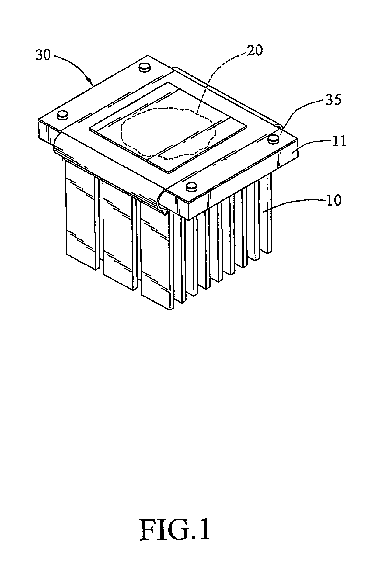
[0023]the invention is shown in FIG. 1, wherein a heat sink fin 10 has a heat sink fin base 11 with a heat-conductive medium 20 placed on the bottom surface thereof, and a protective cover 30 for the heat-conductive medium is disposed on the heat-conductive medium 20 to cover and protect the heat-conductive medium 20.

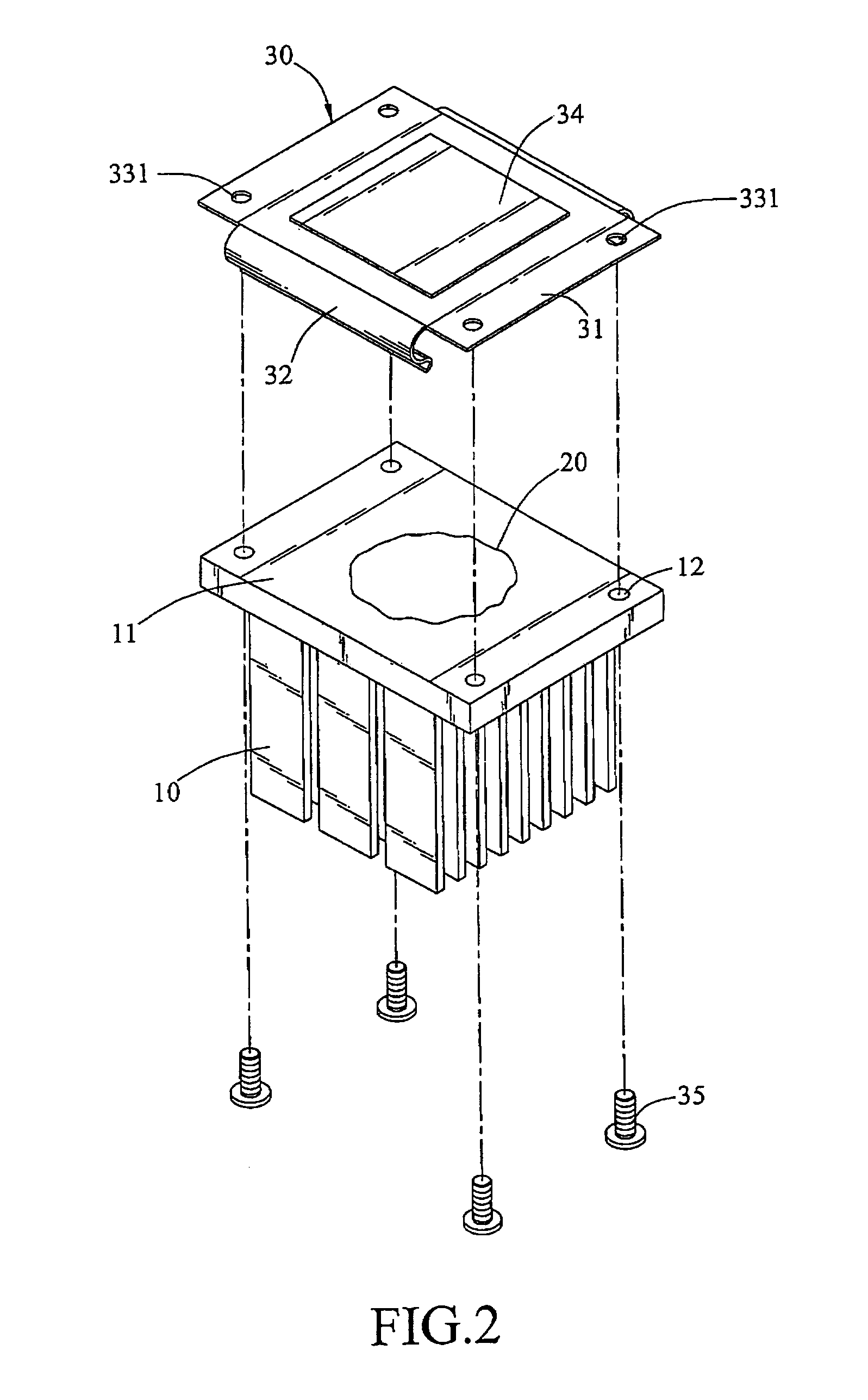
[0024]Referring to FIGS. 2, 3, the heat-conductive medium 20 is placed on the bottom surface of the heat sink fin base 11 with a screwing hole 12 opened thereon. The protective cover 30 for the heat-conductive medium includes a sheet-like board 31, an elastic wall 32 extending along the edge of the sheet-like board 31. The sheet-like board 31 is provided with a fastening portion 33 and an accommodation chamber 34, wherein the fastening portion 33 has a through hole 331 corresponding to the screwing hole 12, and the accommodation chamber 34 protrudes outwards corresponding to the position of the heat-conductive medium 20, so as to mask and cover the heat-conductive mediu...

second embodiment

[0026]the invention is shown in FIG. 4, wherein a heat-conductive medium 20a is placed on the bottom surface of a heat sink fin base 11a with a screwing hole 12a opened thereon; a protective cover 30a for the heat-conductive medium includes a sheet-like board 31a with a star-like positioning hole 331a corresponding to the screwing hole 12a; and the accommodation chamber 34a protrudes outwards corresponding to the position of the heat-conductive medium 20a for masking and covering the heat-conductive medium 20a.

[0027]When the protective cover 30a for the heat-conductive medium is mounted on the heat sink fin base 11a, one side of the sheet-like board 31a moves towards the heat sink fin base 11a, such that both of them can be engaged with each other so as to limit the movement of the sheet-like board 31a in the X, Y, and Z directions. The star-like positioning hole 331a of the sheet-like board 31a is aligned with the screwing hole 12a, with the accommodation chamber 34a being located...

third embodiment

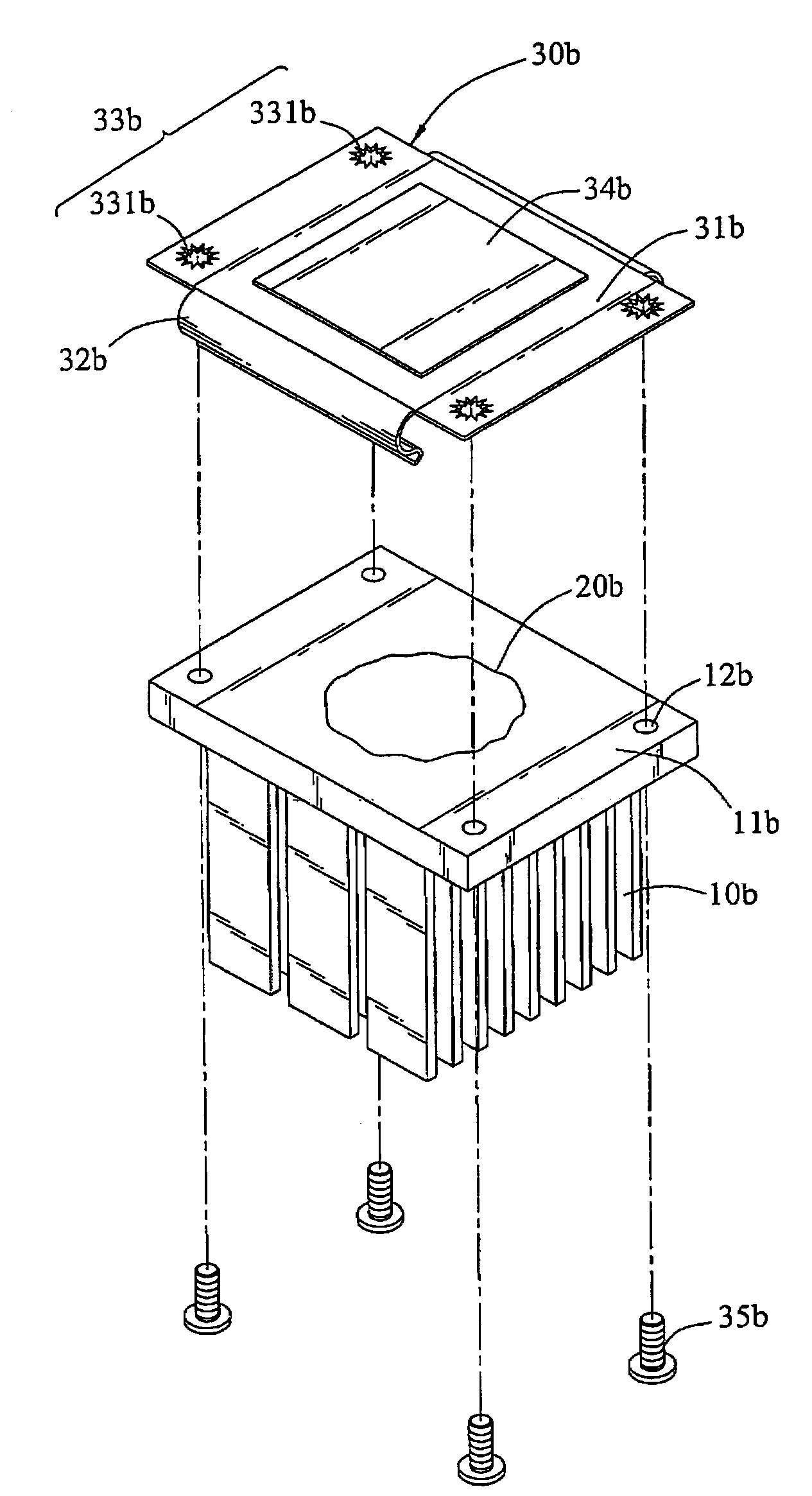
[0028]the invention is shown in FIG. 5, wherein a heat sink fin 10b has a heat sink fin base 11b with a heat-conductive medium 20b placed on the bottom surface, and a protective cover 30b for the heat-conductive medium is disposed on the heat-conductive medium 20b to cover and protect the heat-conductive medium 20b.

[0029]Referring to FIG. 6, the heat-conductive medium 20b is placed on the bottom surface of the heat sink fin base 11b with a screwing hole 12b opened thereon. The protective cover 30b for the heat-conductive medium includes a sheet-like board 31b with an elastic wall 32b extending along the edge. The sheet-like board 31b is provided with a fastening portion 33b and an accommodation chamber 34b, wherein the fastening portion 33b is provided with a star-like positioning hole 331b corresponding to the screwing hole 12b; and the accommodation chamber 34b protrudes outwards corresponding to the position of the heat-conductive medium 20b for masking and covering the heat-con...


PUM


Abstract

A protective cover with a heat-conductive medium of a heat sink apparatus is provided, which is used to cover and protect the heat-conductive medium placed at the bottom surface of a base of the heat sink apparatus. It includes a sheet-like board, an elastic wall, and an accommodation chamber, wherein the sheet-like board is concave and located at one side of the protective cover with the heat-conductive medium; the elastic wall is extended along the edge of the sheet-like board so as to provide a clipping force for clipping with the heat sink apparatus; and the accommodation chamber is formed by the concave portion of the sheet-like board to mask and cover the heat-conductive medium; while the sheet-like board is clipped to the heat sink apparatus through the elastic wall, such that the accommodation chamber is used to mask and cover the heat-conductive medium.

Description

BACKGROUND OF THE INVENTION[0001]1. Field of Invention[0002]The present invention relates to a structural design of a protective cover for a heat-conductive medium, and more particularly to a protective cover for a heat-conductive medium suitable for a heat sink apparatus.[0003]2. Related Art[0004]Electronic elements in the computer apparatus, such as central processing unit (CPU) chips and power integrated circuits (ICs), etc., generate heat when carrying out operations. The watt consumption of CPU chips has become higher and higher, and the high integrity of ICs also centralizes the heat source, such that not only does intense heat occur during the operation, but the resulting heat increases as the operation speed increases. Since the operation temperature has severe impact on whether the computer apparatus will crash or not, appropriate temperature control will provide the computer apparatus with high reliability and allow the heat-emitting electronic elements to operate stably.[...

Claims


Application Information

Patent Timeline
Patent Type & Authority Patents(United States)
IPC IPC(8): H05K7/20
CPCH01L23/4093H01L2023/4068H01L2924/0002H01L2023/4087H01L2924/00
Inventor WANG, FRANKCHENG, YI-LUNFAN, JUI-CHANCHANG, CHUN-YILIN, CHUN-LUNGYANG, CHIH-KAI
Owner INVENTEC CORP
Why Eureka
Try Eureka