Structure for fixing steering-gear housing

a technology for fixing structures and steering gears, which is applied in the direction of instruments, signs, furniture parts, etc., can solve the problems of difficult engagement work difficult to secure the strength of brackets at the engaged portions of main securing bolts, and complicated assembling work for fixing structures. , to achieve the effect of simplifying assembling work and simple structur

Active Publication Date: 2008-01-22
HITACHI ASTEMO LTD
View PDF12 Cites 5 Cited by
  • Summary
  • Abstract
  • Description
  • Claims
  • Application Information

AI Technical Summary

Benefits of technology

[0007]It is, therefore, an object of the present invention to provide a structure for fixing a steering-gear housing to a vehicle-body member, which allows fully secured strength of brackets at engaged portions for a main securing bolt with simple structure, and remarkably simplified assembling work.

Problems solved by technology

However, such fixing structure needs complicated assembling work such that two brackets are previously integrated together by welding or the like, which is then mounted to a vehicle-body member by securing bolts.
Thus, with only the auxiliary securing bolt engaged, the brackets are separated from each other at sites with main bolt holes for receiving the main securing bolts by, principally, a resiliency of the resilient body, resulting in difficult insertion of the main securing bolt into the main bolt holes of the brackets, and thus difficult engaging work of the main securing bolt.
When simply decreasing the length of the main bolt holes, insertion of the main securing bolt into the main bolt holes can be made easily, but the strength of the brackets at engaged portions for main securing bolt is difficult to secure.
On the other hand, when simply increasing the length of the main bolt holes, the strength of the engaged portions of the brackets can be enhanced, but inserting and engaging work of the main securing bolt becomes difficult.
However, the use of a collar leads to not only an increase in the number of parts, but also a necessity of press-fitting work.

Method used


Image

  • Structure for fixing steering-gear housing
  • Structure for fixing steering-gear housing
  • Structure for fixing steering-gear housing

Examples


first embodiment

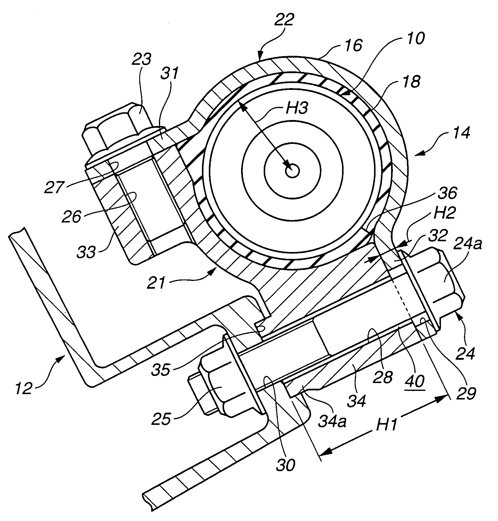
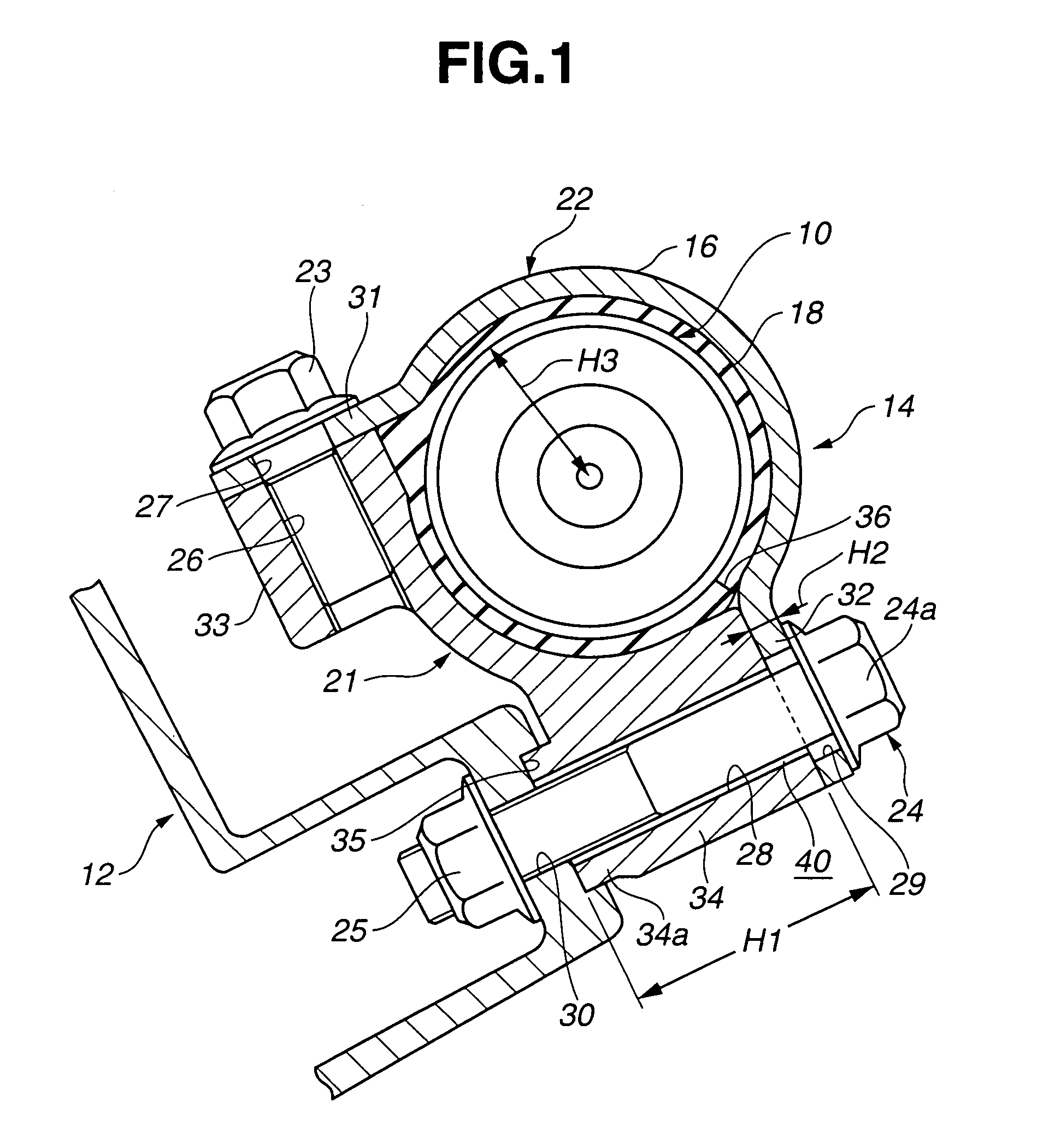
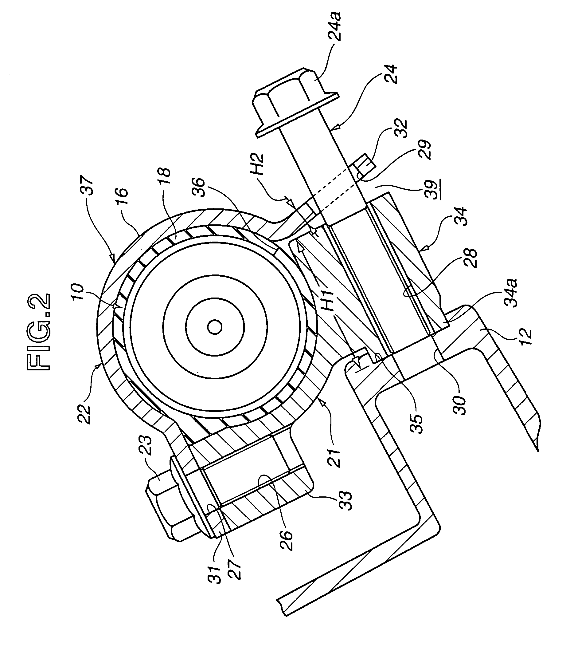
[0024]Referring to FIGS. 1-4C, there is shown first embodiment of the present invention. Referring to FIG. 1, the fixing structure comprises a steering-gear housing 10 for accommodating a steering gear, a suspension member or vehicle-body member 12 to which steering-gear housing 10 is mounted, and a bracket assembly 14 comprising a cylinder portion 16 mounted on the outer periphery of steering-gear housing 10 to surround same and a rubber resilient body 18, such as an insulator, interposed between the inner periphery of cylinder portion 16 and the outer periphery of steering-gear housing 10 in the compressed state to absorb and attenuate vibrations and the like.

[0025]Bracket assembly 14 comprises essentially first and second brackets 21, 22 obtained by circumferentially dividing cylinder portion 16 into two portions, an auxiliary securing bolt or member 23 for securing brackets 21, 22 at one circumferential end, and a main securing bolt or member 24 and nut 25 for securing brackets ...

second embodiment

[0037]Referring to FIGS. 5-8, there is shown second embodiment of the present invention. Referring to FIG. 5, the fixing structure comprises a cylindrical member or steering-gear housing 101 mounted to a support member or suspension member 102. Cylindrical member 101 is held by a pair of brackets 104, 105 through a rubber resilient body 103. First ends of brackets 104, 105 are connected to support member 102.

[0038]First bracket 104 is formed like a relatively thick mass by casting, and includes a roughly 90° curved holder 106 and flanges 107a, 107b arranged on both sides of holder 106 to protrude radially outward.

[0039]Second bracket 105 is formed like a relatively thin mass by press working, and includes a roughly 270° curved holder 108 and flanges 109a, 109b arranged on both sides of holder 108 to protrude radially outward. With flanges 107a, 107b butting on corresponding flanges 109a, 109b so that holders 106, 108 form a circle, brackets 104, 105 are coupled together by securing ...


PUM


Abstract

A fixing structure includes a first bracket having a first bolt hole, a second bracket having a second bolt hole smaller in the axial length than the first bolt hole, a securing member for securing a circumferential end of the first bracket and a circumferential end of the second bracket, and a securing bolt arranged from the second bolt hole through the first bolt hole and for securing the first bracket, the second bracket, and the vehicle-body member together.

Description

BACKGROUND OF THE INVENTION[0001]The present invention relates to a structure for fixing a steering-gear housing to a vehicle-body member.[0002]JP-A 1-244965 discloses a structure for fixing a steering-gear housing to a vehicle-body member by using a pair of brackets or two circumferentially divided portions of a bracket unit. With a resilient body held between the inner periphery of the brackets and the outer periphery of the steering-gear housing in the compressed state, the brackets are previously integrated together by welding or the like to form a bracket unit. The bracket unit is temporarily fixed to the steering-gear housing, then mounted to a vehicle-body member by two securing bolts. However, such fixing structure needs complicated assembling work such that two brackets are previously integrated together by welding or the like, which is then mounted to a vehicle-body member by securing bolts.[0003]Then, in order to achieve simplified assembling work, in place of carrying ou...

Claims


Application Information

Patent Timeline
Patent Type & Authority Patents(United States)
IPC IPC(8): B62D1/16B60G21/055B62D3/12
CPCB60G21/0551B62D3/12B60G2204/1222B60G2204/15B60G2206/60
Inventor MARUYAMA, TATSUYOSHIKANEKO, TAKAHIDE
Owner HITACHI ASTEMO LTD
Why Eureka
Try Eureka