
Light emitting diode light source for curing dental composites

a light source and light source technology, applied in dental surgery, dental tools, manufacturing tools, etc., can solve the problems of composites, current light emitting diodes, composites that produce blue wavelengths, and no heat that can be radiated to the patien

Inactive Publication Date: 2008-01-22
KONINK PHILIPS ELECTRONICS NV
View PDF174 Cites 25 Cited by
  • Summary
  • Abstract
  • Description
  • Claims
  • Application Information

AI Technical Summary

Benefits of technology

[0005]It is an object of the invention to provide a Light Emitting Diode (LED) light source for the curing of dental composite materials that has sufficient power to cure the material and adequate heat management structures to avoid heat damage to the curing light itself and the patient.

Problems solved by technology

Furthermore, Light Emitting Diodes produce no infrared energy and, thereby, produce no heat that can be radiated to the patient.
Unfortunately, current Light Emitting Diodes, that produce the blue wavelengths requisite to cure dental composites, have a low power output (on the order of 5 milliwatts total blue light output).
Furthermore, it is only possible, with current technology, to deliver about 30-40% of the light produced to the dental material.
Further complicating the technology is the low overall efficiency of the Light Emitting Diodes; they are about 6% efficient.
This light is comprised of 7 Light Emitting Diodes which produce, in ideal circumstances, 35 milliwatts of optical curing energy which is insufficient to hit the threshold of 100 milliwatts and as a result does not cure dental composites.
Dental / Medical Diagnostic Systems, Inc. of Wookland Hills, Calif. has invented a Light Emitting Diode curing light that contains over 60 Light Emitting Diodes, however, the device is incapable of dissipating the 4500 milliwatts of thermal energy produced for more than a few seconds, therefore, the device has been found in dentistry to be of little clinical value.
None of the designs adequately manage the heat produced by the Light Emitting Diodes and, subsequently, no working models have been introduced to commerce.
: 6,102,696) which contains insufficient numbers of Light Emitting Diodes to hit the dental composite curing threshold and has no provision for dissipating the heat produced by the Light Emitting Diodes, subsequently, no working models have been introduced to commerce utilizing the design.

Method used


Image

  • Light emitting diode light source for curing dental composites
  • Light emitting diode light source for curing dental composites
  • Light emitting diode light source for curing dental composites

Examples


Embodiment Construction

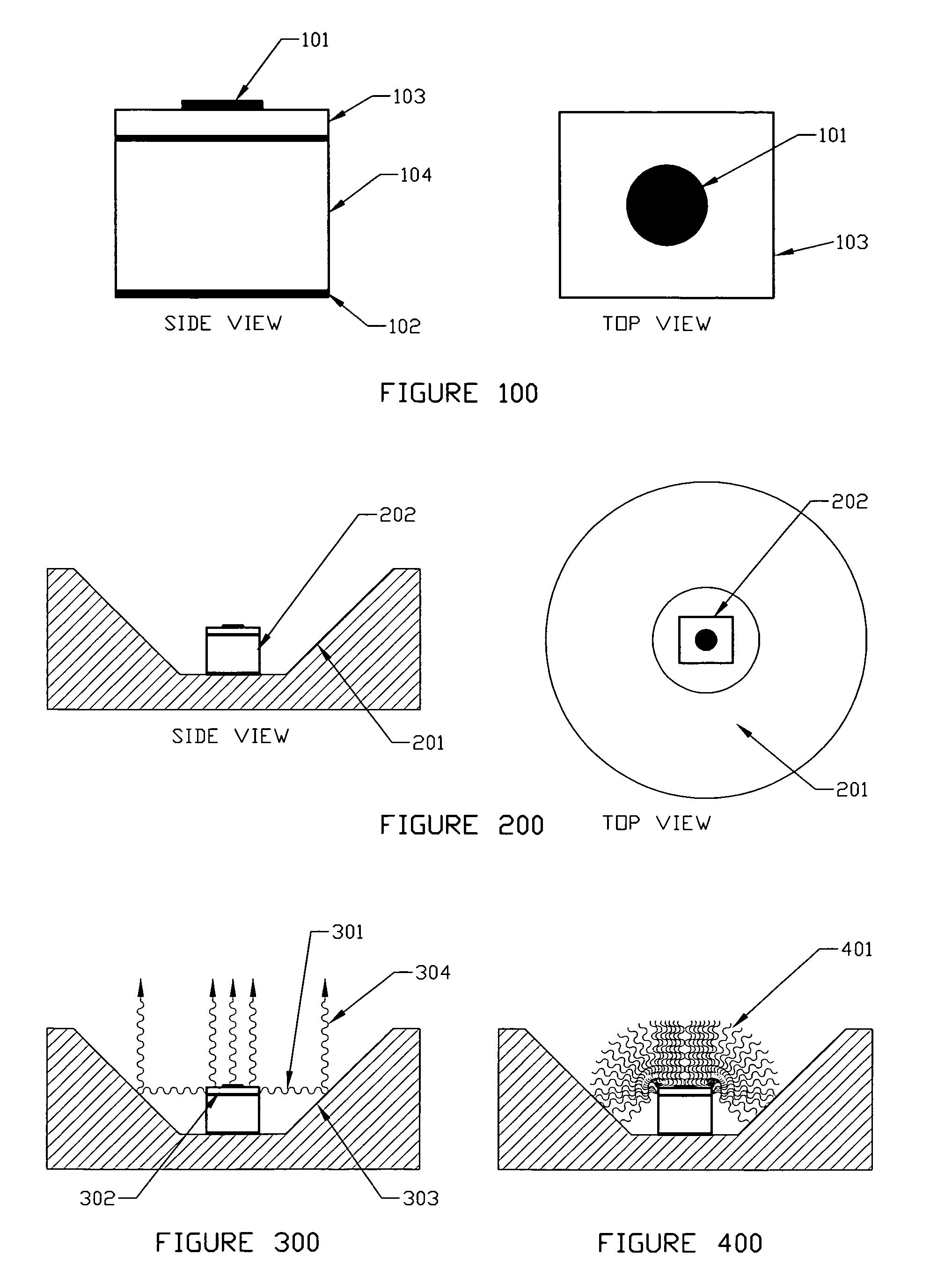
[0059]The invention first takes the LED as an electronic component without any lenses or wires attached, FIG. 100. The LED is essentially a cube with dimensions on the order of 0.250 millimeters, FIG. 100. On the top surface is an Anode (101). The bottom surface is metallized and serves as the Cathode and the heat transfer point / medium (102). The LED also contains a layer of semiconductor that is doped with specific materials in specific concentrations to produce the desired wavelength of light (103). Finally, the LED contains a layer of semiconductor substrate (104). When electrical current is passed between the cathode (102) and the anode (101), photons of a particular wavelength (depending on the composition of the materials) are emitted from the doped semiconductor layer (103).

[0060]Secondly the invention places the LED or LED array on one side of a flat substrate in all configurations of the invention the substrate is both electrically and thermally conductive. This provides th...


PUM


Abstract

Light Emitting Diode Light Sources for Dental Curing are disclosed. Some embodiments of the invention include structures such as Light Emitting Diode Array(s), heat sink, heat dissipation, heat pipe, and control circuitry are disclosed.

Description

PRIORITY: [0001]Priority is hereby claimed to U.S. Provisional Patent Application Ser. No. 60 / 187,899 filed on Mar. 8, 2000.VI. BACKGROUND OF THE INVENTION[0002]This invention relates to the use of Light Emitting Diodes (LEDs) as a light source for curing dental composite materials.VII. THE BACKGROUND ART[0003]Light Emitting Diodes produce a narrow bandwidth of light output wavelengths. Because dental composite materials require specific and narrow bandwidths of light to polymerize correctly attempts have been made to utilize Light Emitting Diodes in dental curing lights. Furthermore, Light Emitting Diodes produce no infrared energy and, thereby, produce no heat that can be radiated to the patient. Unfortunately, current Light Emitting Diodes, that produce the blue wavelengths requisite to cure dental composites, have a low power output (on the order of 5 milliwatts total blue light output). Furthermore, it is only possible, with current technology, to deliver about 30-40% of the li...

Claims


Application Information

Patent Timeline
Patent Type & Authority Patents(United States)
IPC IPC(8): A61C3/00A61C13/15A61N5/06
CPCA61C19/004H05K1/0203H05K1/0209A61N2005/0652H01L2224/48464H01L2224/45144H05K2201/10106H01L2924/00
Inventor OSTLER, CALVIN D.OSTLER, KEVIN D.WALKER, BRUCE R.CIMOLINO, MARC C.ELLEDGE, MILES F.
Owner KONINK PHILIPS ELECTRONICS NV
Learn More