Unlock instant, AI-driven research and patent intelligence for your innovation.

Input circuit for an integrated circuit

a technology of input circuit and integrated circuit, which is applied in the direction of electronic circuit testing, measurement devices, instruments, etc., can solve the problems of considerable noise, slow signal ramps, and input signals applied to the integrated modules are subject to considerable signal disturbances

Inactive Publication Date: 2008-01-22
POLARIS INNOVATIONS LTD
View PDF5 Cites 2 Cited by
  • Summary
  • Abstract
  • Description
  • Claims
  • Application Information

AI Technical Summary

Benefits of technology

[0009]It is an object of the present invention to provide an integrated circuit having an input circuit, in which it is possible to ensure that, when noisy input signals from a burn-in test system are applied, the burn-in test mode can be set in the integrated modules, and in which the input circuit is simultaneously suitable for the high operating frequencies during normal operation.
[0013]A setting circuit may also be provided in order to write a second value to the setting memory on the basis of a received signal sequence so that the second receiving circuit is activated. This makes it possible to provide the integrated circuit in such a manner that it first connects the first receiving circuit to the input terminal after said integrated circuit has been completed. If it is indicated, in accordance with a signal sequence, that the burn-in mode has been concluded, the setting circuit is used to change the value stored in the setting memory so that the second receiving circuit is connected to the input terminal.
[0014]The setting memory is preferably configured in such a manner that the second value is permanently stored after the second value has been written to said setting memory. In particular, the setting memory may be configured in such a manner that it prevents further writing after the second value has been written to it. This rules out the possibility of the end user writing to the setting memory, by applying a suitable signal sequence, in such a manner that the first receiving circuit is connected to the input terminal and the integrated module has impaired properties under certain circumstances. Alternatively, provision may be made for the setting circuit to prevent further writing to the setting memory after the second value has been written to the latter.

Problems solved by technology

However, when initializing and driving the integrated modules which are to be tested in the burn-in method, only very slow signal ramps are possible since the tester channels provided for this purpose are simultaneously connected to a plurality or all of the integrated modules.
In addition, the tester channels have a considerable amount of noise on account of their length, with the result that the input signals which are applied to the integrated modules are subjected to considerable signal disturbances.
Noise in a clock signal or in a reference voltage signal may be interpreted as an additional clock pulse in the integrated modules, which may impair communication between the burn-in test system and the integrated modules.
An additionally interpreted clock pulse or a disturbance in a signal when applying the signal sequence for setting the burn-in mode in the integrated module may result in one of the signals in the particular signal sequence being detected twice during the test mode input sequence, with the result that the burn-in mode is not assumed under certain circumstances.
In this case, the integrated module is not subjected to the burn-in test operation, with the result that the integrated module is not properly pre-aged.
However, input circuits having such high hysteresis are disadvantageous and are too slow for integrated modules having high transmission rates since the maximum operating frequency of the integrated modules is limited by the high hysteresis.

Method used


Image

  • Input circuit for an integrated circuit
  • Input circuit for an integrated circuit
  • Input circuit for an integrated circuit

Examples


Embodiment Construction

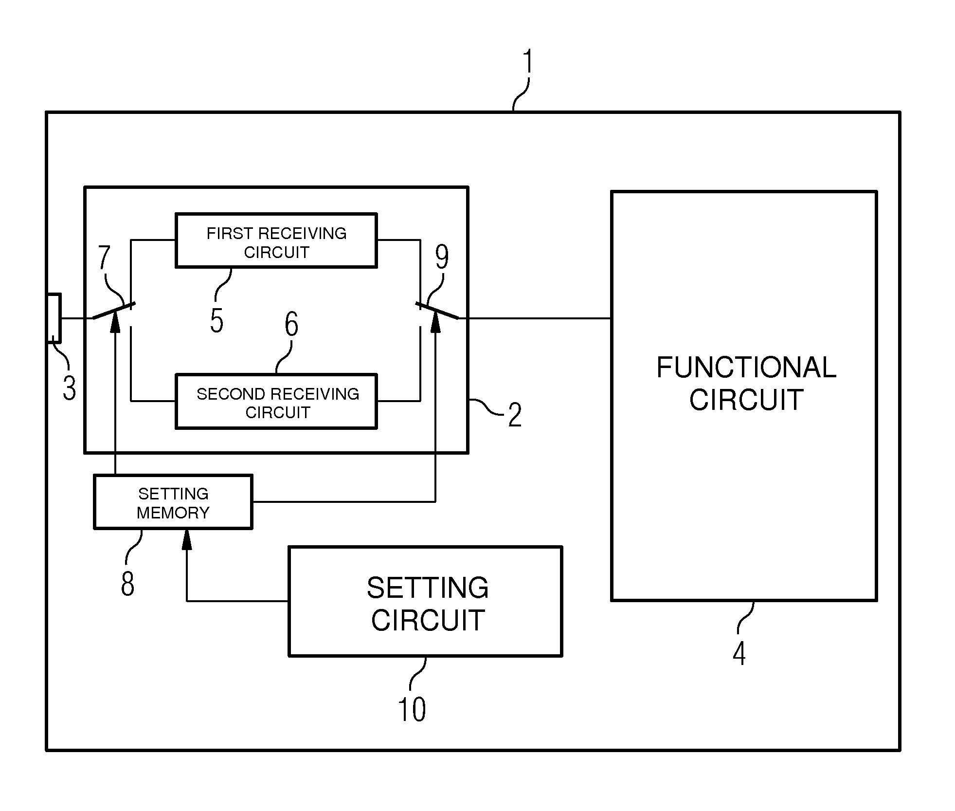
[0021]FIG. 1 diagrammatically illustrates a block diagram of an integrated circuit 1 having an input circuit 2 in order to receive an input signal that is applied to an input terminal 3 and to provide a functional circuit 4 with said signal for processing the received signals further. In the exemplary embodiment shown, only one input circuit 2 is illustrated. However, it goes without saying that integrated circuits usually have a multiplicity of such input circuits. The functional circuit 4 may be any desired circuit selected from a logic circuit, a memory circuit, a sensor circuit and the like which may be integrated in the integrated circuit 1.

[0022]The input circuit 2 has a first receiving circuit 5 and a second receiving circuit 6. Both the first and the second receiving circuit 5, 6 can be connected to the input terminal 3 via a switch 7. The switch 7 is driven by an output of a setting memory 8, with the result that the information stored in the setting memory 8 determines the...


PUM


Abstract

An integrated circuit includes a functional circuit, a setting memory for storing a setting data item and an input circuit for receiving signals via an input terminal. The input circuit includes a first receiving circuit having first hysteresis and a second receiving circuit having second hysteresis wherein the input circuit connects either the first or the second receiving circuit to the input terminal on the basis of the setting data item in order to receive the signals and to provide the functional circuit with the signals.

Description

CROSS-REFERENCE TO RELATED APPLICATIONS[0001]This application claims foreign priority benefits under 35 U.S.C. § 119 to co-pending German patent application number DE 10 2004 057 819.2, filed 1 Dec. 2004. This related patent application is herein incorporated by reference in its entirety.BACKGROUND OF THE INVENTION[0002]1. Field of the Invention[0003]The invention relates to an integrated circuit having an input circuit for receiving signals via an input terminal. In particular, the invention relates to an integrated circuit which can be put into a burn-in mode in order to pre-age the integrated circuit and which can be operated in a conventional manner after the burn-in operation.[0004]2. Description of the Related Art[0005]In conventional burn-in test systems for carrying out a burn-in method, a plurality of integrated modules are simultaneously subjected to a stress condition and are tested in the process. However, when initializing and driving the integrated modules which are to...

Claims


Application Information

Patent Timeline
Patent Type & Authority Patents(United States)
IPC IPC(8): G01R31/02
CPCG01R31/2856G11C29/1201G11C29/46
Inventor KRACH, MARKUS
Owner POLARIS INNOVATIONS LTD