Coordinate input device having non-flat operation surface and electronic apparatus

Inactive Publication Date: 2008-01-22
ALPS ALPINE CO LTD
View PDF19 Cites 26 Cited by
  • Summary
  • Abstract
  • Description
  • Claims
  • Application Information

AI Technical Summary

Benefits of technology

[0018]As described above, according to the coordinate input device of the present invention, the coordinate input operation is performed by sliding the operating member on a capacitive sensor substrate, and the operation surface for sliding the operating member is formed in a concave shape, a convex shape, or the shape of a polyhedron. Accordingly, the user obtains not only the sense of two-dimensional movement but also the sense of vertical movement along the curved surface from his or her finger sliding on the operation surface. Thus, the amount and direction of finger movement can be easily recognized, so that the coordinate input operation can be performed more finely and

Problems solved by technology

However, when the above-described flat touch pad 205 is used, since the coordinate input operation is performed by moving a finger on the touch pad 205, there is a problem in that it is difficult for the user to feel the sense of

Method used


Image

  • Coordinate input device having non-flat operation surface and electronic apparatus
  • Coordinate input device having non-flat operation surface and electronic apparatus
  • Coordinate input device having non-flat operation surface and electronic apparatus

Examples


first embodiment

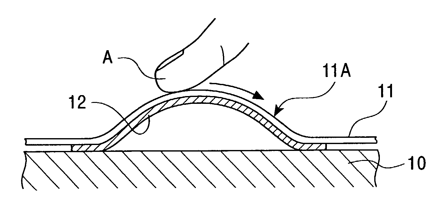
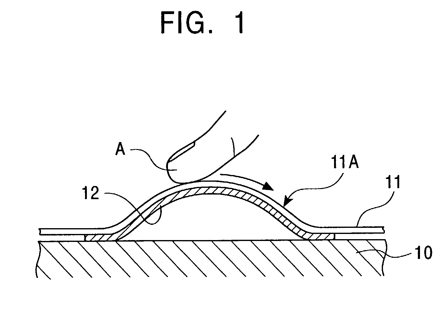
[0040]FIG. 1 shows a sectional view of a coordinate input device according to a first embodiment of the present invention. The coordinate input device shown in the figure includes a cover 11 and a sensor substrate 12. The cover 11 has a convex portion 11A and is formed on a base 10, and the sensor substrate 12 has the shape corresponding to the convex portion 11A and is laminated on the bottom surface of the convex portion 11A (surface facing the base 10) of the cover 11.

[0041]As shown in FIG. 3B, the sensor substrate 12 is formed by laminating an upper substrate 14 and a lower substrate 15. The upper substrate 14 is provided with an electrode layer 16 on the top surface thereof (that is, the surface facing opposite to the lower substrate 15). As shown in FIG. 3B, the electrode layer 16 includes a plurality of line electrodes 16a arranged parallel to each other in a striped pattern in a plan view. In addition, the lower substrate 15 is provided with an electrode layer 17 on the top ...

second embodiment

[0054]Next, a second embodiment of the present invention will be described below with reference to FIGS. 5 to 7. FIG. 5 is a sectional view of a coordinate input device according to the second embodiment, and FIG. 6 is a sectional view of a coordinate input device according to a modification of the second embodiment. FIG. 7 is a perspective view of the coordinate input device shown in FIG. 5.

[0055]The coordinate input device shown in FIGS. 5 and 7 includes a detection sensor unit 32 formed on a base 30 and an operation unit 33 formed on the detection sensor unit 32. The operation unit 33 includes a base plate 33a and a hemispherical operation member 33b which is attached on top of the base plate 33a. The coordinate input device is installed inside a housing 35 such that the upper side of the operation member 33b projects outside through a hole 36 formed in the housing 35.

[0056]In addition, as shown in FIG. 7, the detection sensor 32 includes four strain gauges 34 which are arranged ...


PUM


Abstract

A coordinate input device includes a coordinate input unit which performs a coordinate input operation by sliding an operating member on an operation surface which is formed in a convex shape, a concave shape, or the shape of a polyhedron. More specifically, the coordinate input device includes a capacitive sensor substrate formed by laminating two electrode layers with an upper substrate (dielectric layer) therebetween, each electrode layer including a plurality of electrodes arranged in a striped pattern. In addition, the coordinate input device also includes the operation surface formed in a convex (or concave) shape which is used for performing a coordinate input operation by sliding the operating member thereon.

Description

BACKGROUND OF THE INVENTION[0001]1. Field of the Invention[0002]The present invention relates to coordinate input devices used in electronic apparatuses such as computers, mobile phones or game devices for moving a cursor or a character, selecting a function, etc., on a display, and also relates to electronic apparatuses including the coordinate input devices.[0003]2. Description of the Related Art[0004]FIG. 15 is a perspective view of a notebook personal computer having a coordinate input device called a touch pad in front of a keyboard. This computer 200 includes a main body 201 and a display 203 which is connected to the main body 201 by a hinge at the rear end of the main body 201. A keyboard 204, a touch pad (coordinate input device) 205, and operation buttons 206 are provided on the top surface of the main body 201. The touch pad 205 has a flat, rectangular shape and is disposed in front of the keyboard 204, and the operation buttons 206 are disposed in front of the touch pad ...

Claims


Application Information

Patent Timeline
IPC IPC(8): G06F3/041G06F3/033G06F3/0346G06F3/0354G06F3/038G06F3/044
CPCG06F3/0338G06F3/044G06F3/0446G06F3/0445
Inventor SATO, TADAMITSUSOMA, MASAHIRO
Owner ALPS ALPINE CO LTD
Why Eureka
Try Eureka