Soft stent with excellent follow-up capability to blood vessel

a soft stent and follow-up capability technology, applied in the field of soft stents, can solve the problems of difficult introduction of the stent into the objective site, obstructing or stenosis of the lumen, and stents that have sufficient flexibility, and achieve excellent radial expansionability, excellent trackability to the lumen, and easy production of shortening

Inactive Publication Date: 2008-01-29
NIPRO CORP
View PDF24 Cites 30 Cited by
  • Summary
  • Abstract
  • Description
  • Claims
  • Application Information

AI Technical Summary

Benefits of technology

[0013]According to the present invention, the stent has potential for providing the following effects: (1) the whole stent is flexible to bending and thus excellent in trackability to lumens since the annular members that form a tubular wall of the stent are composed of repeated snaky patterns of an annular member element (i.e., a unit pattern); (2) the stent is hard to produce shortening since the adjoining two annular members are connected between junctions where the first annular member elements and second annular member elements of the respective annular members are connected, in a manner, at the middle positions of wavelike patterns with the coupling elements; (3) the stent is excellent in radial expandability, easy to provide a lateral hole since the annular members that form a tubular wall of the stent are composed of repeated circumferentially continuing wavy patterns. Also, the stent is excellent in balance at the time of expansion since the stent expands uniformly along the entire length of the stent.

Problems solved by technology

These stents have been improved to some extent, but they still put a load on the lumen such as the blood vessel in the vicinity of edges of the expanded stent, resulting in obstruction or stenosis of the lumen.
Further, it can not be said that these stents have sufficient flexibility, and thus it is often difficult to introduce the stent into the objective site if the lumen has a three-dimensionally meandering course.
In addition, the stents may cause wounds in the blood vessel during insertion into the objective site.
If there is a branched blood vessel at the inflated position, it is hardily difficult to form a lateral hole in the placed stent.

Method used


Image

  • Soft stent with excellent follow-up capability to blood vessel
  • Soft stent with excellent follow-up capability to blood vessel
  • Soft stent with excellent follow-up capability to blood vessel

Examples


embodiment

Embodiment 1

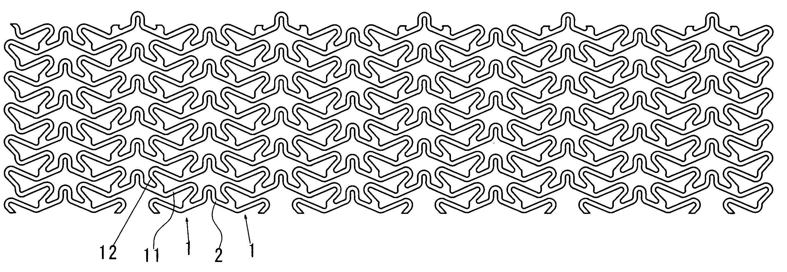
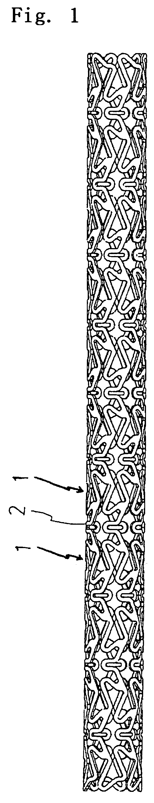
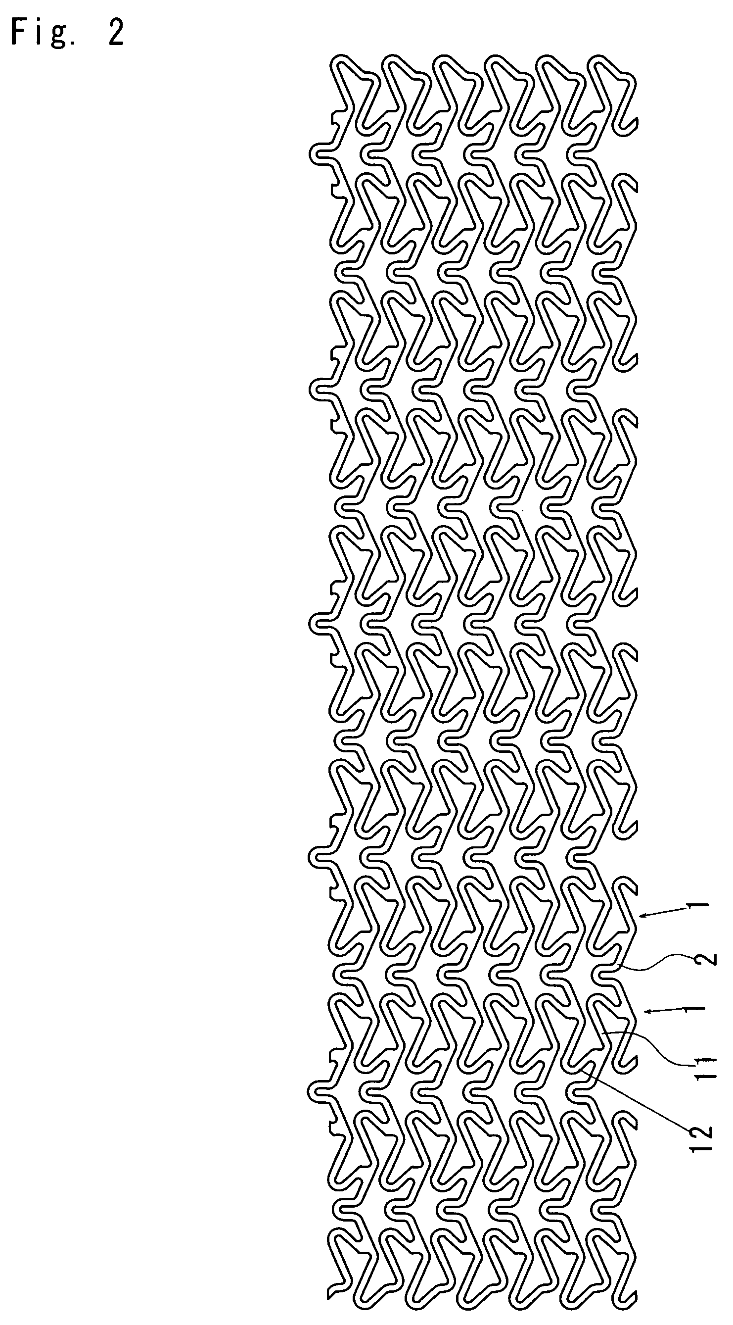
[0049]FIG. 1 is an enlarged plan view of a stent according to embodiment 1 of the present invention, FIG. 2 is a development of the stent shown in FIG. 1, FIG. 3 is an enlarged plan view illustrating an expanded state of the stent shown in FIG. 1, and FIG. 4 is a partially enlarged view of FIG. 2.

[0050]As shown in FIGS. 1 to 3, the stent of embodiment 1 comprises eleven annular members 1 which are radially expandable and arranged in the longitudinal direction of the stent. The adjoining annular members 1, 1 are longitudinally connected with six coupling elements 2 of a pattern as shown in FIG. 5A. Each annular member 1 comprises first annular member elements 11 and second annular member elements 12, which have plane symmetrical patterns and are alternately connected in the circumferential direction by a connecting segment 15. Under the condition that the stent is unfolded onto a plane, the first annular member element 11 has a wave mountain (a wave which is convex rightw...

embodiment 2

[0054]Embodiment 2 of the present invention will be demonstrated below, making reference to FIG. 6.

[0055]The stent of embodiment 2 is a modification of the stent of embodiment 1, wherein the coupling elements are formed into a pattern as illustrated in FIG. 5B. As illustrated in FIG. 6, the stent comprises eleven annular members 1 and the adjoining two annular members 1, 1 are coupled with six coupling elements 2 of a pattern shown in FIG. 5B. The adjoining two annular members 1, 1 are coupled between the junctions 16 of the right annular member 1 and the junctions 17 of the left annular member 1 with the coupling elements 2.

[0056]The stent of this embodiment is superior to that of embodiment 1 in flexibility for bending, and thus it is excellent in trackability to lumens. Further, the stent hardly produces shortening of the length and is high in radial expandability. In addition, the stent makes it easy to provide a lateral hole and shows good structural balance at the time of expa...

embodiment 3

[0057]Embodiment 3 of the present invention will be demonstrated below, making reference to FIG. 7.

[0058]The stent of embodiment 3 is a modification of the stent of embodiment 1, in which first annular member elements 11 and second annular member elements 12 are aligned parallel with the longitudinal axis of the stent. The stent includes twelve annular members 1 and coupling elements 2 formed into a pattern as illustrated in FIG. 5C. As illustrated in FIG. 7, the stent comprises twelve annular members 1 which are radially expandable and are arranged in the longitudinal direction of the stent. The adjoining two annular members 1, 1 are longitudinally connected with six coupling elements 2 of a pattern shown in FIG. 5C.

[0059]The annular member 1 includes pairs of relatively long upper linear segments 111 , 121 and relatively short lower linear segments 112, 122, which are parallel with the longitudinal axis of the stent. The upper linear segment 111, 121 of one pair is respectively co...


PUM


Abstract

To provide a lumen-friendly, flexible stent which is excellent in trackability to lumens (thus, it is able to pass through the three-dimensionally meandering lumens), substantially free from shortening (shortening of the length), uniformly expandable.A stent according to the present invention comprises radially expandable annular members (1) which are aligned in a longitudinal direction of the stent, and one or more coupling elements (2) that couple adjoining two annular members (1) in the longitudinal direction of the stent, wherein said annular member comprises first annular member elements (11) and second annular member elements (12), which have a plane symmetrical pattern and are alternately connected in the circumferential direction of the annular member, and wherein under the condition that the stent is unfolded onto a plane, the first annular member element (11) includes one wave mountain, while the second annular member element (12) includes one wave trough, the adjoining two annular members being connected between the junctions which connect the first annular member elements (11) and second annular member elements (12) of the respective annular members.

Description

TECHNICAL FIELD[0001]The present invention relates to a stent that is implanted in a human body to maintain a diameter of a body lumen such as blood vessels.BACKGROUND ART[0002]So far, stents have been used to expand a diameter of the body lumen such as the blood vessel and keep it to the expanded luminal diameter. The stent may be expanded by various methods such as balloon dilation, self-expansion using a shape memory material, mechanical expansion, or the like. The most widely used method is the balloon dilation. In the balloon dilation, a stent is introduced into a desired site in the body together with a balloon catheter, expanded by inflation of balloon to dilate a diameter of the lumen, and retained at the dilated site even after removing the deflated balloon from the site. The stent generally comprises luminal diameter-holding portions for dilating and holding the diameter of the lumen such as blood vessel, and joint portions for connecting the luminal diameter-holding porti...

Claims


Application Information

Patent Timeline
Patent Type & Authority Patents(United States)
IPC IPC(8): A61F2/06A61F2/91A61F2/915
CPCA61F2/91A61F2/915A61F2002/91533A61F2002/9155A61F2002/91558A61F2002/91575
Inventor SANO, YOSHIHIKO
Owner NIPRO CORP
Why Eureka
Try Eureka