Fan fixture and housing assembly containing the fan fixture

a technology of fan fixture and housing assembly, which is applied in the direction of auxillary pretreatment, instruments, separation processes, etc., can solve the problems of reducing the working efficiency and lifetime of electronic parts, affecting the cleaning effect of filters, and inconvenience for users in assembly, so as to facilitate user mounting and detaching the fan, and facilitate cleaning the filter

Active Publication Date: 2008-01-29
GIGA BYTE TECH CO LTD
View PDF16 Cites 39 Cited by
  • Summary
  • Abstract
  • Description
  • Claims
  • Application Information

AI Technical Summary

Benefits of technology

[0007]Another objective of the present invention is to provide a fan fixture, wherein the snapping hooks of the cover are detachably snapped into the slots of the frame so that the cover can be mounted on and detached from the frame easily and rapidly, thereby greatly facilitating a user mounting and detaching the fan.
[0008]A further objective of the present invention is to provide a fan fixture, wherein the filter of the fan fixture covers the air inlet of the frame to provide a dustproof effect so as to prevent the dust or insects from entering the fan to protect the fan and the electronic parts contained in the housing.
[0009]A further objective of the present invention is to provide a fan fixture, wherein the filter is detachably mounted on the top cover and the frame, so that the filter can be directly removed from the top cover to facilitate the user cleaning the filter.
[0010]A further objective of the present invention is to provide a fan fixture, wherein the two opposite protruding wings of the filter net cover the receiving hole of the top cover to prevent the dust or insects from entering the receiving hole of the top cover.

Problems solved by technology

However, the housing is not provided with a cover to cover the vent holes of the housing, so that the dust or insects will easily enter the inside of the housing by the attractive force of the fan to break the electronic parts contained in the housing, thereby decreasing the working efficiency and lifetime of the electronic parts.
However, the above-mentioned conventional filter device has a complicated construction and cannot be mounted on the housing easily and conveniently, thereby causing inconvenience to a user in assembly, replacement and maintenance of the conventional filter device.

Method used


Image

  • Fan fixture and housing assembly containing the fan fixture
  • Fan fixture and housing assembly containing the fan fixture
  • Fan fixture and housing assembly containing the fan fixture

Examples


Embodiment Construction

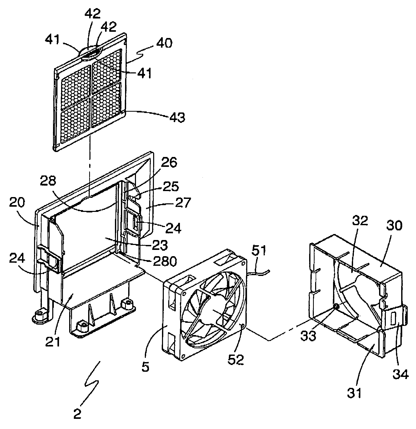
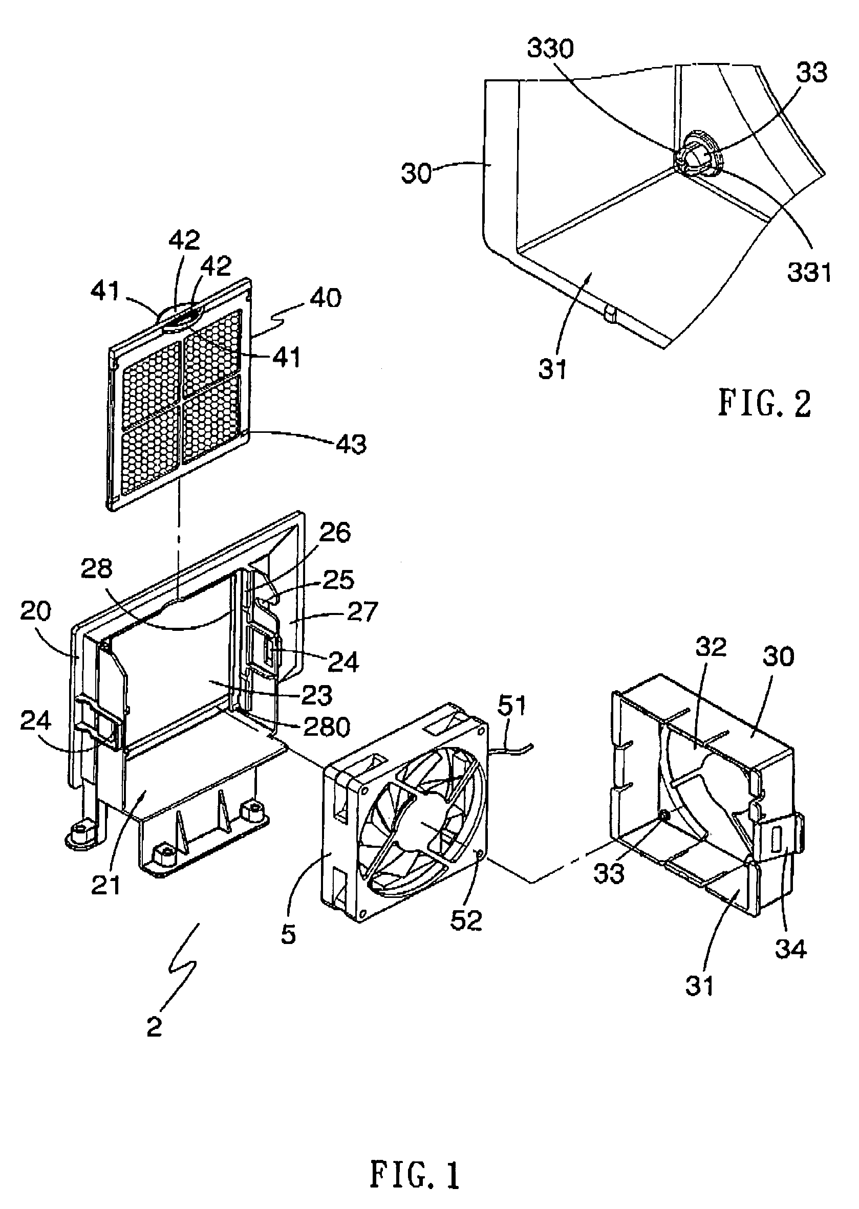
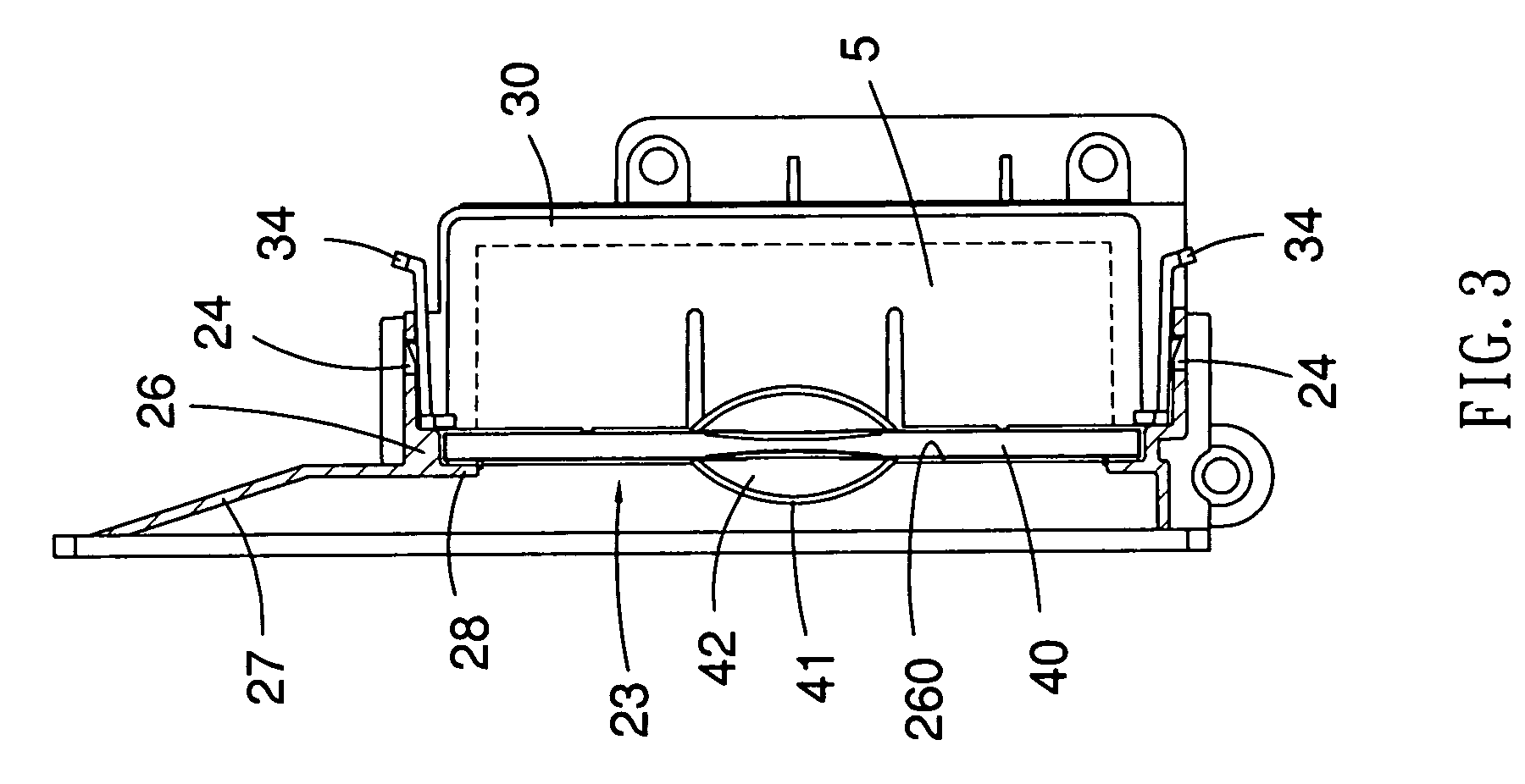
[0023]Referring to the drawings and initially to FIGS. 1 and 2, a fan fixture 2 in accordance with the preferred embodiment of the present invention comprises a frame 20, a cover 30, and a filter 40.

[0024]The frame 20 has a chamber 21 to receive a fan 5 which has an electric wire 51 and a plurality of holes 52. The frame 20 includes an air inlet 23 in communication with the chamber 21. Thus, the fan 5 introduces ambient air from the air inlet 23 into the chamber 21 of the frame 20. The chamber 21 of the frame 20 is defined between two opposite side walls each formed with a slot 24, and one of the two opposite side walls of the chamber 21 of the frame 20 has a breach 25 to allow passage of the electric wire 51 of the fan 5.

[0025]The cover 30 is disposed in the chamber 21 of the frame 20 and has a receiving space 31 to receive a fan 5. The receiving space 31 of the cover 30 has a bottom face having a central portion formed with a plurality of air outlets 32 to vent the air and four co...


PUM

PropertyMeasurementUnit
flexibilityaaaaaaaaaa
flexibleaaaaaaaaaa
widthaaaaaaaaaa

Abstract

A fan fixture includes a base having a chamber to receive a fan, the chamber of the base having two adjacent side faces formed with a slot and an air inlet respectively, a cover detachably mounted on the base to fix the fan in the chamber of the base and having a plurality of air outlets, and a filter net inserted through the slot into the chamber of the base to cover the air inlet of the base. Thus, the filter net of the fan fixture covers the air inlet of the base to provide a dustproof effect so as to prevent the dust or insects from entering the fan to protect the fan and the electronic parts contained in the housing.

Description

BACKGROUND OF THE INVENTION[0001]1. Field of the Invention[0002]The present invention relates to a fan fixture, and more particularly to a fan fixture for a housing assembly of a computer.[0003]2. Description of the Related Art[0004]A conventional housing assembly of a computer comprises a housing, a plurality of electronic parts mounted in the housing, and a fan mounted in a side wall of the housing to introduce ambient air from the vent holes in the side wall of the housing into the inside of the housing to provide a heat dissipation effect to the electronic parts contained in the housing. However, the housing is not provided with a cover to cover the vent holes of the housing, so that the dust or insects will easily enter the inside of the housing by the attractive force of the fan to break the electronic parts contained in the housing, thereby decreasing the working efficiency and lifetime of the electronic parts.[0005]A conventional filter device for the housing assembly of a c...

Claims


Application Information

Patent Timeline
Patent Type & Authority Patents(United States)
IPC IPC(8): B01D50/00
CPCB01D46/0005B01D46/10G06F1/20H05K7/20181B01D2273/30Y10S55/31
Inventor FU, TUNG-CHENG
Owner GIGA BYTE TECH CO LTD
Why Eureka
Try Eureka