Methods and apparatus for alleviating deadlock in a fibre channel network

a fibre channel network and deadlock technology, applied in the field of network congestion control, can solve the problems of poor control of end and buffer-to-buffer flow, high undesirable packet dropping, rough technique, etc., and achieve the effect of reducing deadlock and congestion and effective reduction of deadlock

Active Publication Date: 2008-01-29
CISCO TECH INC
View PDF9 Cites 23 Cited by
  • Summary
  • Abstract
  • Description
  • Claims
  • Application Information

AI Technical Summary

Benefits of technology

[0008]Methods and apparatus are provided for alleviating deadlock and controlling congestion in a network such as a fibre channel network. Techniques are provided for detecting stalled frames at a fibre channel switch. Reserve credits are released when stalled frames are detected. In some instances, reserve credits are released after a predetermined period of time. Reserve credits allow transmission to effectively reduce deadlock and congestion. Reserve credits are particularly effective in reducing deadlock resulting from transient loops in a fibre channel network.

Problems solved by technology

In networks such as fibre channel networks, packet dropping is generally highly undesirable.
End-to-end and buffer-to-buffer flow control mechanisms do not allow a first network node to transmit to a second network node until a second network node is ready to receive a frame.
However, end-to-end and buffer-to-buffer flow control mechanisms provide only a very rough technique for controlling congestion, as the mechanism blocks all traffic along a particular link.
Such blocking can lead to deadlock, a situation where two or more switches are unable to transmit because the switches are no longer able to receive additional frames.
However, buffer space cannot be freed until the second switch can transmit to the first switch that also has a full buffer.
Hence, congestion at one link of one network path can sometimes cause blocking over a much wider portion of a fibre channel topology.

Method used


Image

  • Methods and apparatus for alleviating deadlock in a fibre channel network
  • Methods and apparatus for alleviating deadlock in a fibre channel network
  • Methods and apparatus for alleviating deadlock in a fibre channel network

Examples


Embodiment Construction

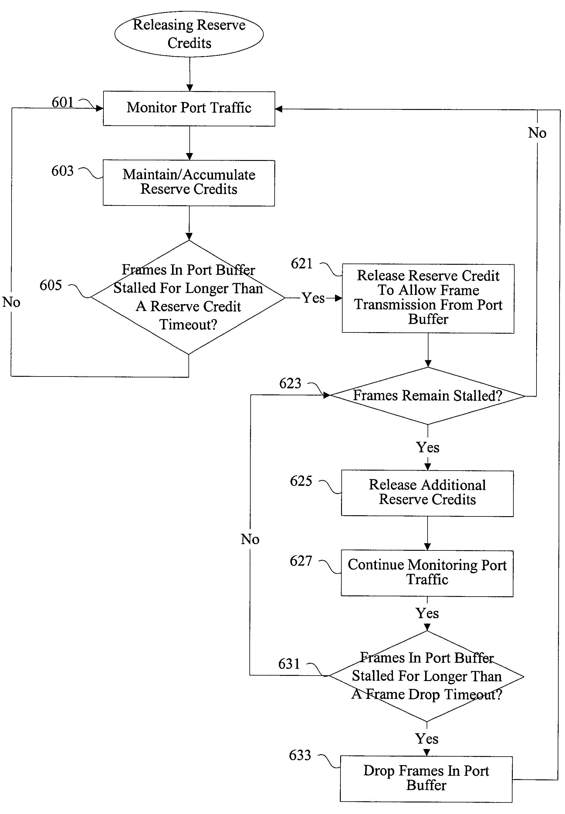
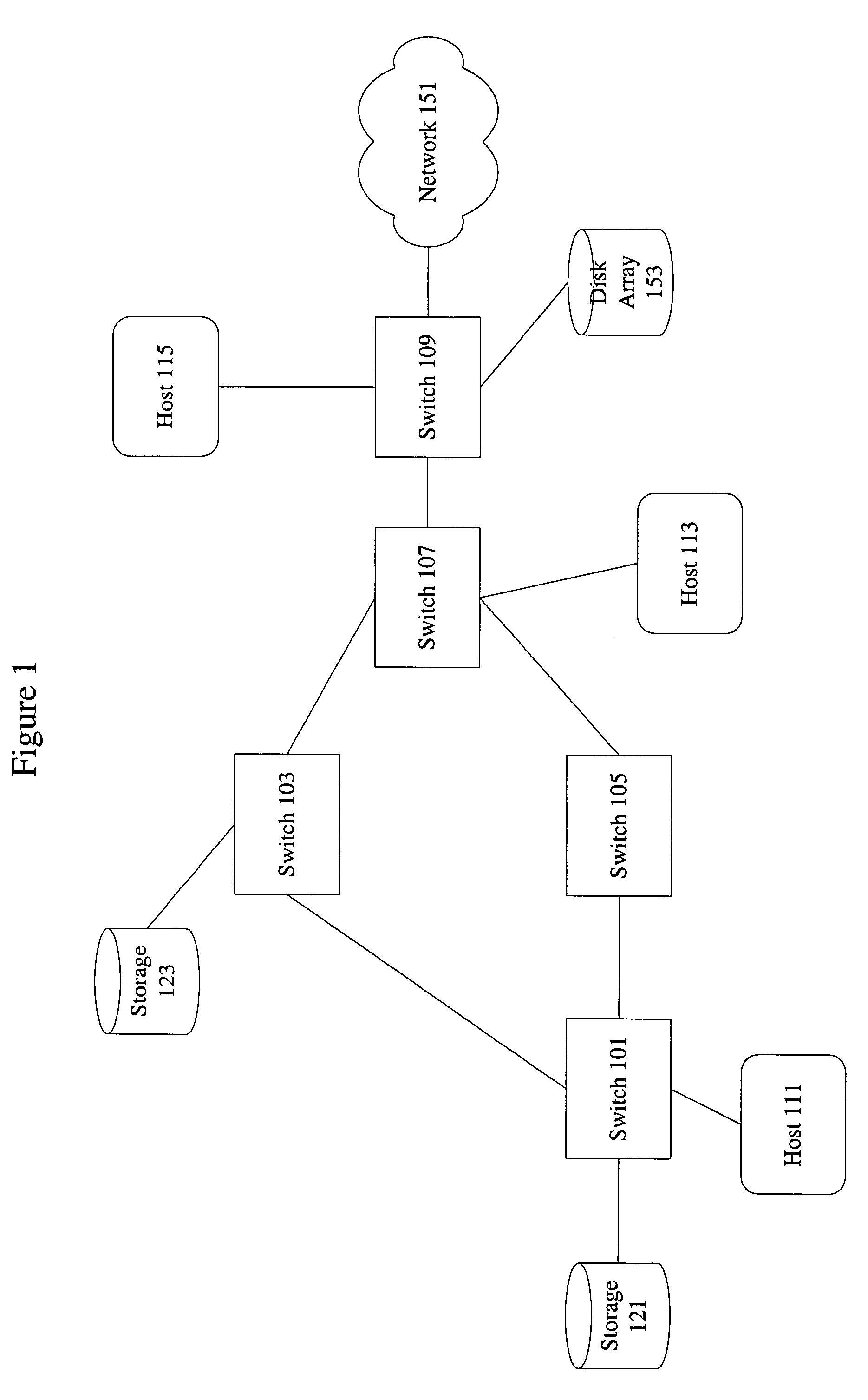
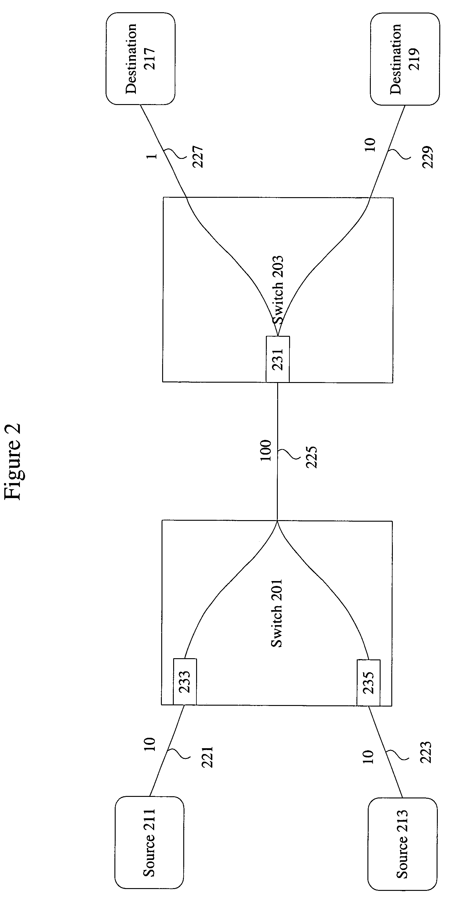
[0023]Reference will now be made in detail to some specific embodiments of the invention including the best modes contemplated by the inventors for carrying out the invention. Examples of these specific embodiments are illustrated in the accompanying drawings. While the invention is described in conjunction with these specific embodiments, it will be understood that it is not intended to limit the invention to the described embodiments. On the contrary, it is intended to cover alternatives, modifications, and equivalents as may be included within the spirit and scope of the invention as defined by the appended claims.

[0024]For example, the techniques of the present invention are particularly effective in alleviating deadlock resulting from transient loops in a fibre channel network. However, the techniques of the present invention can be applied to not only deadlock resulting from transient loops, but deadlock and congestion in general. Furthermore, the techniques of the present inv...


PUM


Abstract

Methods and apparatus are provided for alleviating deadlock and controlling congestion in a network such as a fibre channel network. Techniques are provided for detecting stalled frames at a fibre channel switch. Reserve credits are released when stalled frames are detected. In some instances, reserve credits are released after a predetermined period of time. Reserve credits allow transmission to effectively reduce deadlock and congestion. Reserve credits are particularly effective in reducing deadlock resulting from transient loops in a fibre channel network.

Description

BACKGROUND OF THE INVENTION[0001]1. Field of the Invention[0002]The present invention relates to network congestion control. More specifically, the present invention relates to methods and apparatus for detecting and alleviating conditions such as deadlock.[0003]2. Description of Related Art[0004]Many conventional network protocols use packet dropping to alleviate congestion at a network node. In one example, a network node in an IP based network receives input data from multiple sources at a rate exceeding its output bandwidth. In conventional implementations, selected packets are dropped to allow transmission of remaining packets within the allocated output bandwidth. Packets can be dropped randomly or dropped using various selection criteria. The dropped packets are ultimately retransmitted under the control of a higher level protocol such as TCP.[0005]In networks such as fibre channel networks, packet dropping is generally highly undesirable. Instead, networks such as fibre chan...

Claims


Application Information

Patent Timeline
Patent Type & Authority Patents(United States)
IPC IPC(8): H04J1/16H04J3/14
CPCH04L47/10H04L47/39
Inventor KLOTH, RAYMOND J.COMETTO, MAURILIO
Owner CISCO TECH INC
Why Eureka
Try Eureka