Color segmentation-based stereo 3D reconstruction system and process

a 3d reconstruction and color segmentation technology, applied in image analysis, instruments, computing, etc., can solve the problems of affecting the quality of 3d reconstruction, the most noticeable artifacts, and the quality of resolution of most of today's algorithms that is not required by these applications, so as to improve the results of segmentation and improve the quality of segmentation

Inactive Publication Date: 2008-01-29
MICROSOFT TECH LICENSING LLC
View PDF4 Cites 38 Cited by
  • Summary
  • Abstract
  • Description
  • Claims
  • Application Information

AI Technical Summary

Benefits of technology

[0011]It is noted that improved results can be achieved if prior to the foregoing segmentation of the images, the color differences between adjacent pixels of each image are smoothed. This entails in one embodiment of the invention employing the following smoothing technique for each pixel in raster order. Namely, each possible grouping of a prescribed number (e.g., 3) of contiguous pixels neighboring the pixel under consideration is selected in turn, and for each selected group of pixels, the intensity of the color of each pixel in the selected group is subtracted from the intensity of the color of the pixel under consideration. The squared values of the resulting differences are summed to produce a total difference for the selected group. The group of pixels exhibiting the smallest total difference is then identified and the color of each of the pixels in the identified group and that of the pixel under consideration are averaged. The resulting average color is then assigned to the pixel under consideration as its current color. It is noted that the foregoing color smoothing procedure can be repeated a prescribed number of times to improve the results of the segmentation even further.

Problems solved by technology

Unfortunately, the quality and resolution of most of today's algorithms falls quite short of that demanded by these applications.
For example, traditional stereo algorithms tend to produce erroneous results around disparity discontinuities.
Unfortunately, such errors produce some of the most noticeable artifacts in interpolated scenes, since disparity discontinuities typically coincide with intensity edges.

Method used


Image

  • Color segmentation-based stereo 3D reconstruction system and process
  • Color segmentation-based stereo 3D reconstruction system and process
  • Color segmentation-based stereo 3D reconstruction system and process

Examples


Embodiment Construction

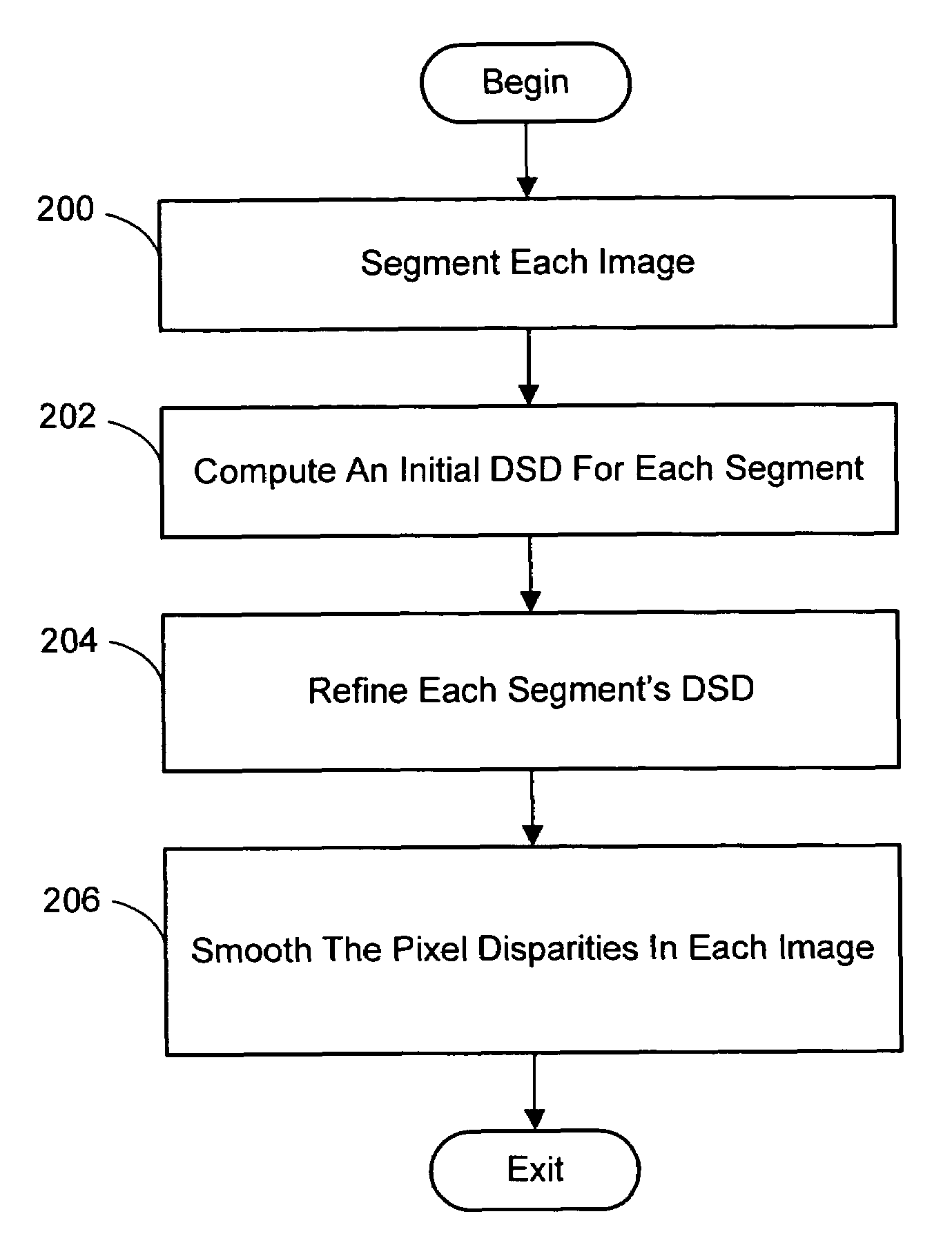
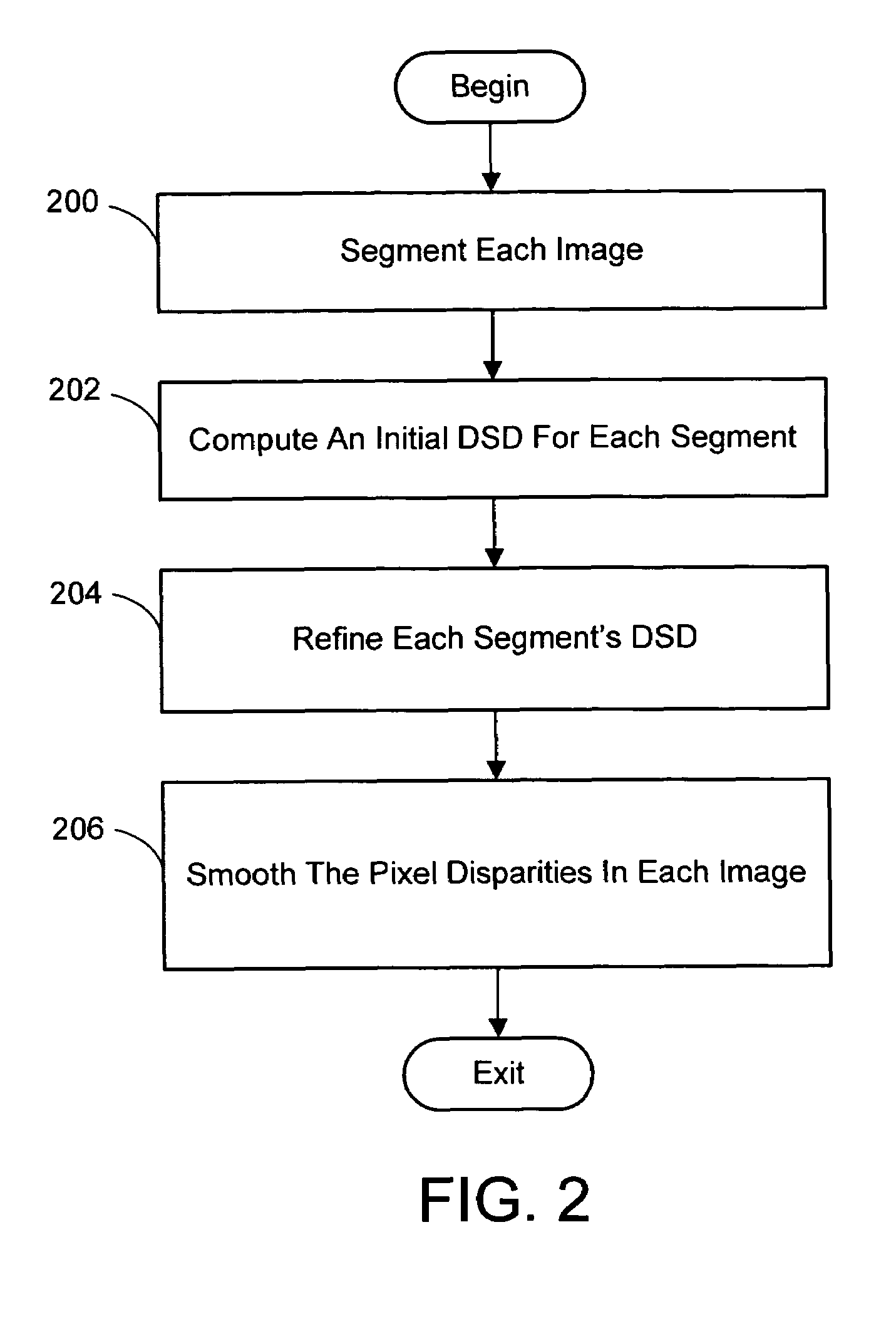
[0034]In the following description of the preferred embodiments of the present invention, reference is made to the accompanying drawings which form a part hereof, and in which is shown by way of illustration specific embodiments in which the invention may be practiced. It is understood that other embodiments may be utilized and structural changes may be made without departing from the scope of the present invention.

1.0 The Computing Environment

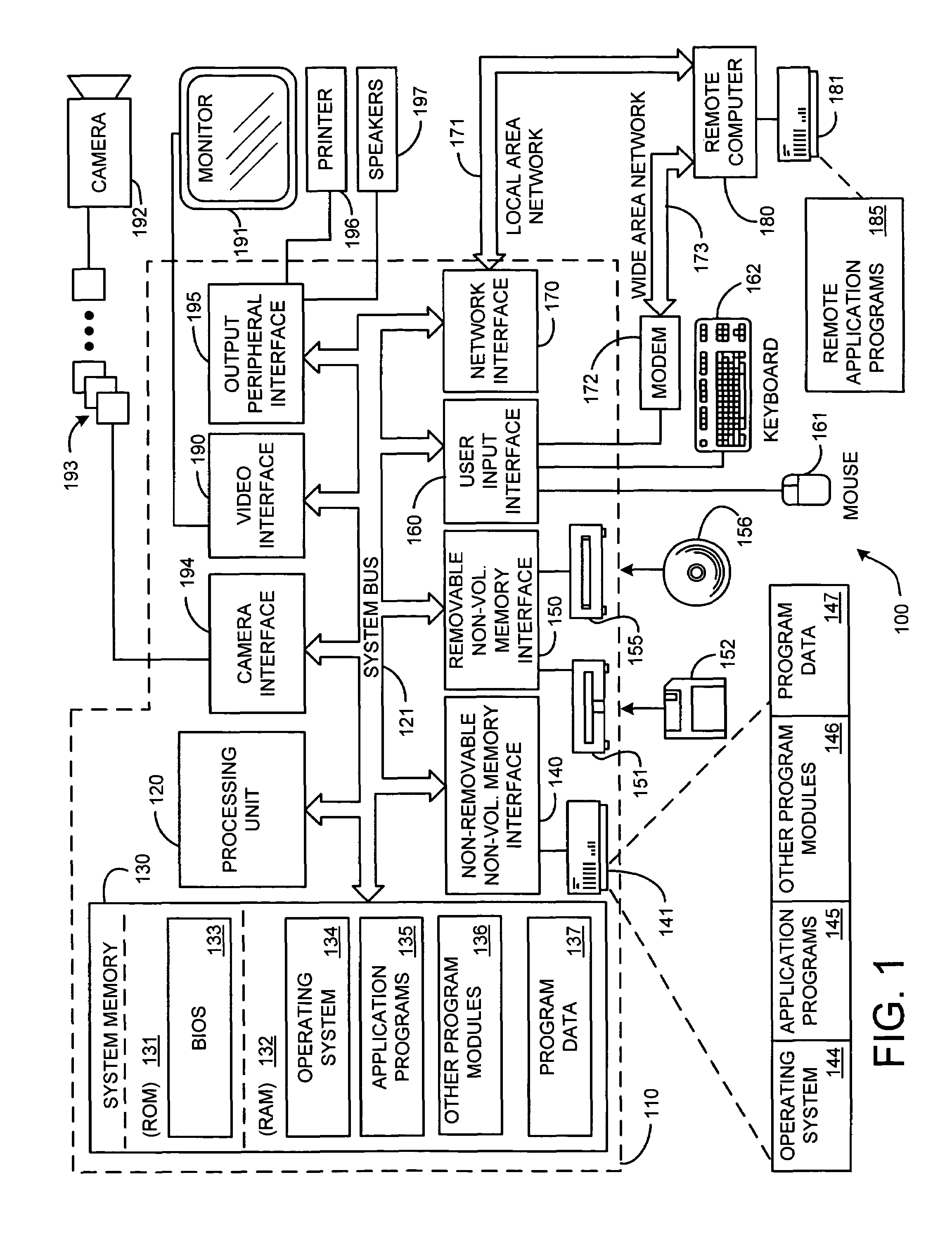
[0035]Before providing a description of the preferred embodiments of the present invention, a brief, general description of a suitable computing environment in which the invention may be implemented will be described. FIG. 1 illustrates an example of a suitable computing system environment 100. The computing system environment 100 is only one example of a suitable computing environment and is not intended to suggest any limitation as to the scope of use or functionality of the invention. Neither should the computing environment 100 be interpre...


PUM


Abstract

A system and process for computing a 3D reconstruction of a scene from multiple images thereof, which is based on a color segmentation-based approach, is presented. First, each image is independently segmented. Second, an initial disparity space distribution (DSD) is computed for each segment, using the assumption that all pixels within a segment have the same disparity. Next, each segment's DSD is refined using neighboring segments and its projection into other images. The assumption that each segment has a single disparity is then relaxed during a disparity smoothing stage. The result is a disparity map for each image, which in turn can be used to compute a per pixel depth map if the reconstruction application calls for it.

Description

BACKGROUND[0001]1. Technical Field[0002]The invention is related to 3D reconstruction of a scene using multiple images thereof, and more particularly to a system and process for computing such a 3D reconstruction using a color segmentation-based approach.[0003]2. Background Art[0004]Stereo reconstruction generally involves using multiple images taken from different viewpoints to reconstruct a 3D model of the scene depicted in the images. Typically, this reconstruction entails recovering depth maps (often for each image) and identifying corresponding pixels between the images. These reconstructions are used for a variety of purposes. For example, depth maps obtained from stereo have been combined with texture maps extracted from input images in order to create realistic 3-D scenes and environments for virtual reality and virtual studio applications. Similarly, these maps have been employed for motion-compensated prediction in video processing applications. Still further, the recovere...

Claims


Application Information

Patent Timeline
Patent Type & Authority Patents(United States)
IPC IPC(8): G06K9/00G06T7/00G06T19/00G06V10/10
CPCG06K9/20G06T7/0065G06K2209/40G06T7/55G06V10/10G06V2201/12G06T15/10G06T7/00
Inventor ZITNICK, III, CHARLESKANG, SING BINGUYTTENDAELE, MATTHEWWINDER, SIMONSZELISKI, RICHARD
Owner MICROSOFT TECH LICENSING LLC
Why Eureka
Try Eureka