
Multi-axial base isolation system

a base isolation and multi-axial technology, applied in the direction of high internal friction springs, vehicle components, resilient suspensions, etc., can solve the problems of not being able to address the problems of prior art, and not being able to provide multi-axial

Active Publication Date: 2008-02-05
ENIDINE
View PDF36 Cites 20 Cited by
  • Summary
  • Abstract
  • Description
  • Claims
  • Application Information

AI Technical Summary

Benefits of technology

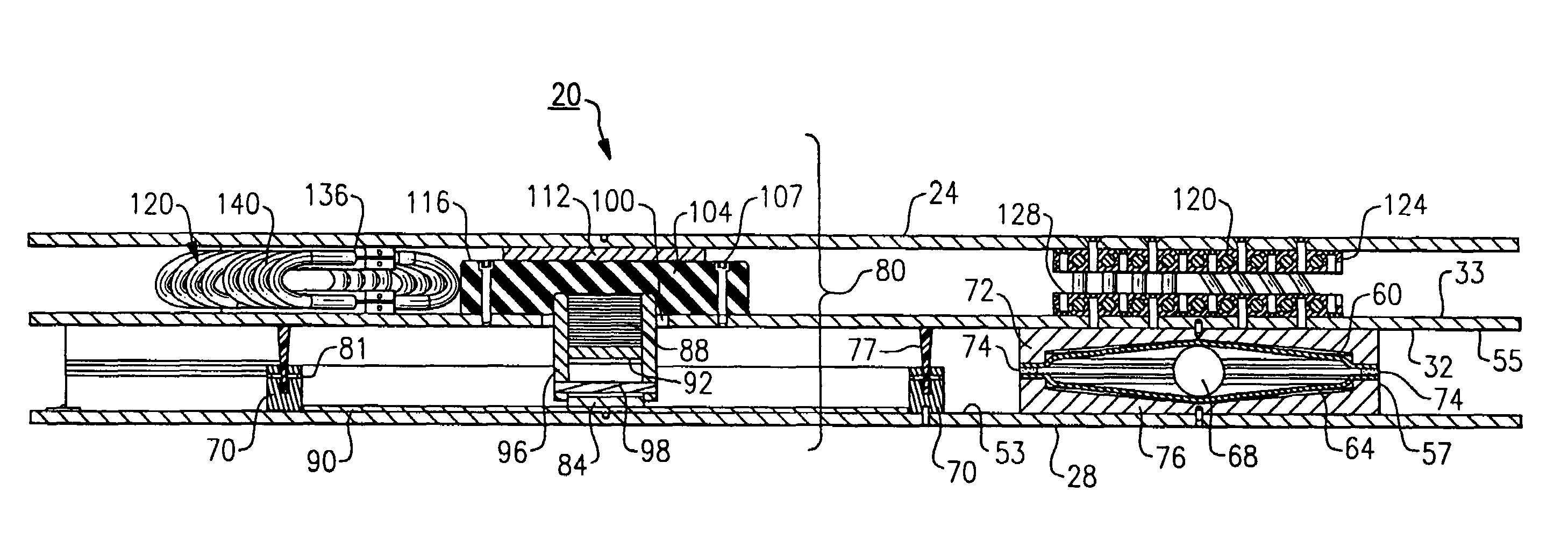
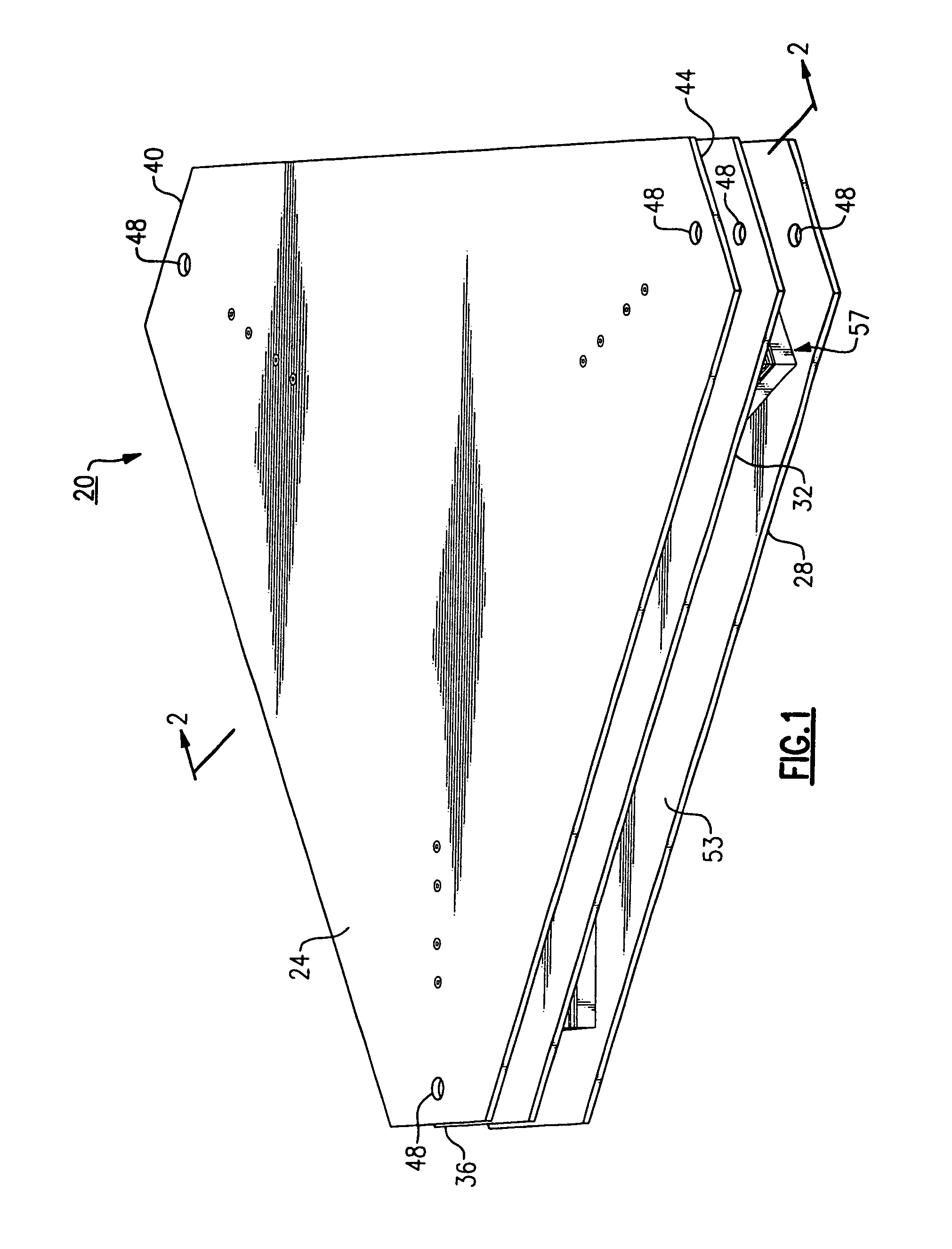
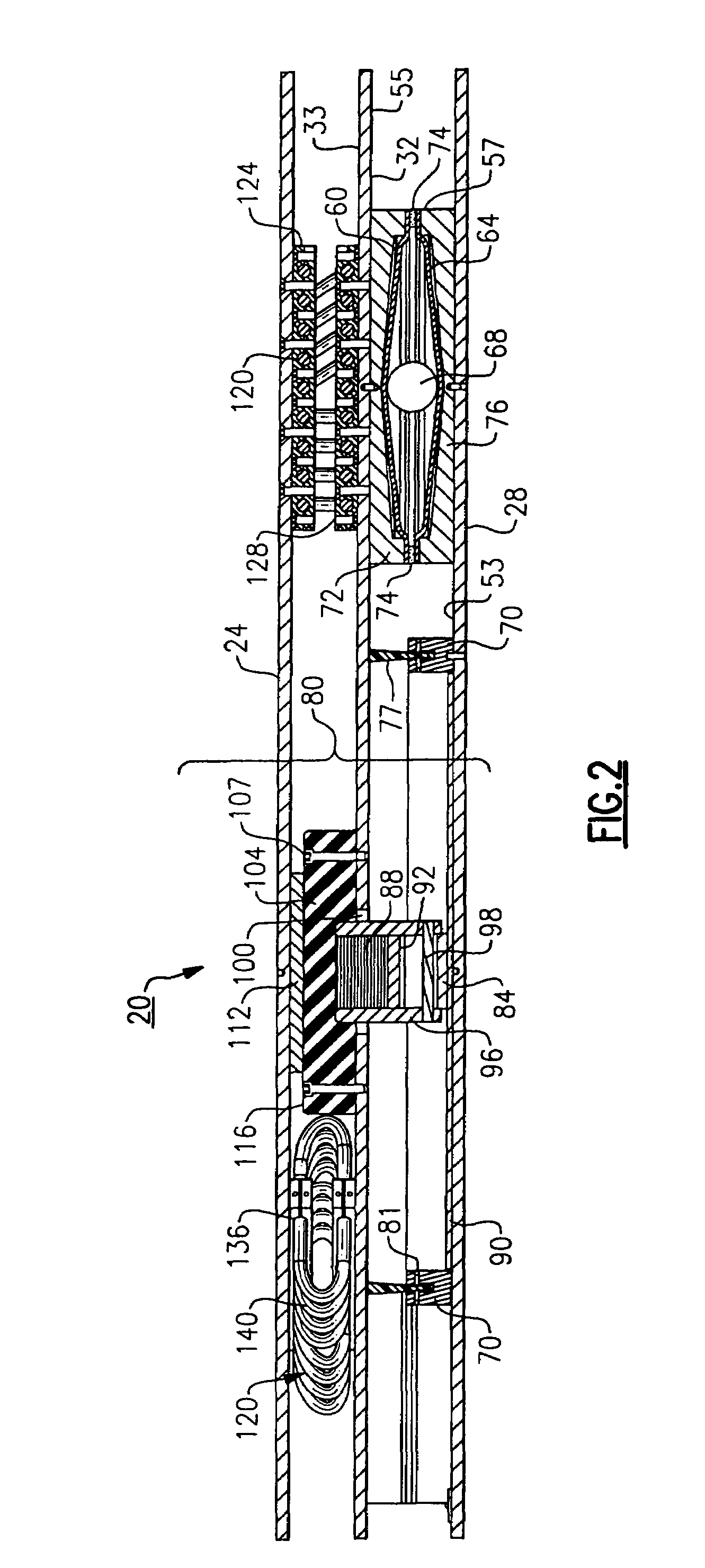
"The present invention provides a multi-axial motion isolation system for components that can isolate both horizontal and vertical motions in a single integrated assembly. The system includes a first isolation subsystem and a second isolation subsystem that work together to provide isolation from lateral and vertical loads or motions. The first isolation subsystem includes ball and cone isolators and a friction producing device, while the second isolation subsystem includes wire rope isolators and an elastomeric pad. The system can be used to isolate components from seismic events or other multi-axial loads. The invention allows for effective isolation of components from multi-axial loads or motions using a single integrated apparatus."

Problems solved by technology

Though the preceding references provide a single form of isolation, Applicant is currently unaware of any available system that provides multi-axial (i.e., horizontal and vertical) isolation systems or assemblies in order to properly protect, for example, non-structural equipment.
In addition, none of the preceding patents, or any known prior art as presently understood by Applicants, appear to address issues, such as those relating to horizontal friction and / or overtravel limitations using such isolation apparatus, for proper field application of such components or for preventing sand, dirt, and other contaminants from potentially degrading such apparatus.

Method used


Image

  • Multi-axial base isolation system
  • Multi-axial base isolation system
  • Multi-axial base isolation system

Examples


Embodiment Construction

[0029]The following description relates to a multi-axial isolation system that is made in accordance with a preferred embodiment of the present invention for use with a specific component. It will be readily apparent from the following discussion, however, that many variations and modifications are possible to one of sufficient skill in the field within the intended scope of the present invention. In addition, several terms are used throughout the course of discussion such as, for example “top”, “bottom”, “above”, “below”, “upper”, “lower”, and the like in order to provide a convenient frame of reference with regard to the accompanying drawings. It is not intended, however, unless specifically indicated otherwise, that these terms are intended to be overly limiting of the present invention.

[0030]Referring to FIG. 1, the multi-axial isolation system in accordance with this specific embodiment of the invention is shown in a top perspective view thereof. The system, generally referred ...


PUM


Abstract

A load isolation system for a component includes at least one isolation assembly. The at least one isolation assembly includes a first mounting plate and a second mounting plate, each of which are parallel to one another and are structurally connected to one another. At least two isolation subsystems are integrated into the isolation assembly in which a first isolation subsystem is disposed between the first mounting plate and an intermediate plate for isolating the component from lateral motions and a second isolation subsystem is disposed between the intermediate plate and the second mounting plate for isolating vertical motions in which the first mounting plate is attached to a fixed support and the second mounting plate is attached to the component.

Description

FIELD OF THE INVENTION[0001]This invention relates to the field of base isolation systems, and in particular to a system for isolating multi-axial motion, such as seismic inputs and other events, for use on equipment.BACKGROUND OF THE INVENTION[0002]Several isolation systems are known in the field, such as those, for example, that are described by U.S. Pat. No. 1,761,659 to Cummings, U.S. Pat. No. 2,014,643 to Bakker, U.S. Pat. No. 4,881,350 to Wu, U.S. Pat. No. 5,599,106 to Kemeny and U.S. Pat. No. 6,321,492 to Robinson. Each of the preceding references describes a system that commonly isolates various motions, using a configuration that includes at least one ball bearing provided within halves of a supporting frame, wherein one half of the frame is securely attached to the foundation of a building, bridge or other structure and the remaining half is securely attached to the structure. These described systems are used in order to provide horizontal or lateral isolation, primarily f...

Claims


Application Information

Patent Timeline
Patent Type & Authority Patents(United States)
IPC IPC(8): B60G11/52
CPCF16F1/065F16F3/10F16F15/04
Inventor SIINO, MICHAEL A.BUCHOLTZ, BRIAN C.
Owner ENIDINE
Learn More