Heads-up speed display for vehicles

a head-up speed display and vehicle technology, applied in the direction of identification means, bicycle equipment, instruments, etc., can solve the problems of preventing the operator of a jet ski, snowmobile or trail bike from reading a speedometer, affecting the course of a trail bike, and affecting the operation of a jet ski, snowmobile or trail bik

Inactive Publication Date: 2008-02-05
INVISION SYST
View PDF13 Cites 60 Cited by
  • Summary
  • Abstract
  • Description
  • Claims
  • Application Information

AI Technical Summary

Problems solved by technology

For example, a fallen tree or boulder may impede the course of a trail bike.
Similarly, partially submerged tree limbs, barrels, rope, etc. may constitute an unexpected obstacle to a jet ski.
The degree of surface roughness encountered in off-road travel frequently makes it difficult or impossible for the operator of a jet ski, snowmobile or trail bike to read a speedometer due to the driver's and the vehicle's relative movement.
If the operator of an off-road vehicle, such as a snowmobile, exceeds a safe speed range for the particular combination of skill level, trail and weather conditions, accidents and injuries can result.

Method used


Image

  • Heads-up speed display for vehicles
  • Heads-up speed display for vehicles
  • Heads-up speed display for vehicles

Examples


Embodiment Construction

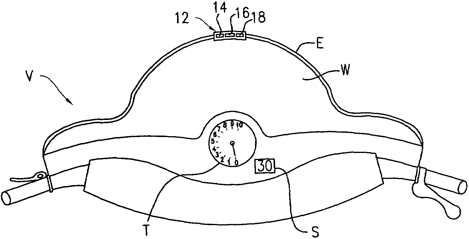
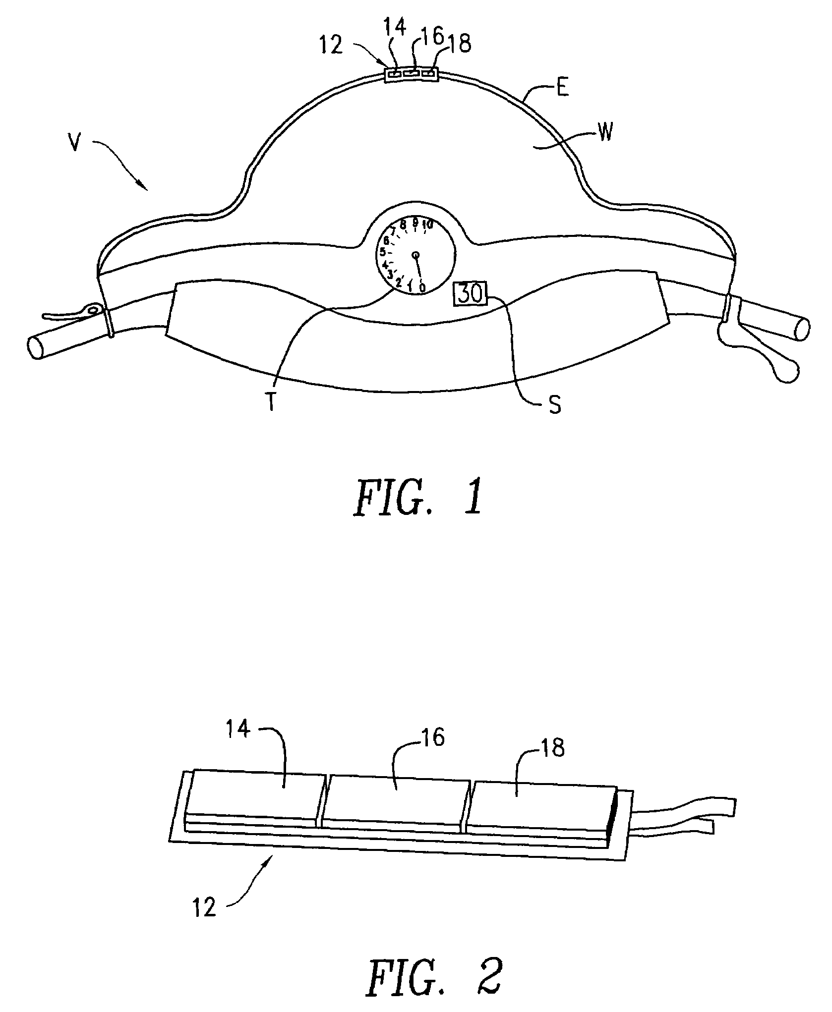
[0016]FIG. 1 shows a vehicle V, such as a snowmobile or an ATV as seen by an operator thereof. i.e., looking forward, out the front windshield W. The snowmobile V has a tachometer T and a speedometer S. In the vehicle V shown, the tachometer T has a dial indicator and the speedometer S has a digital (numeral) readout. The speedometer S may be utilized by the operator to determine the speed of the vehicle V over the terrain on which it is operated. The position of the speedometer S requires the operator to direct his sight down, away from the windshield W in order to determine the speed of the vehicle. As noted above, clear visualization of the speedometer S may also be impeded by movement and weather conditions. A speed indicator 12 in accordance with the present invention is attached to the edge E of the windshield W. Because the speed indicator 12 is positioned on the windshield, it is not necessary for the operator to look down in order to see it. In contrast, the operator may co...


PUM


Abstract

A heads-up speed sensing display and control system for apprising an operator of the risk of operating a vehicle at various speeds has a risk indicator display with a plurality of illuminable elements, such as three different colored LEDs, illuminable in a plurality of patterns, each of the plurality of patterns having a predetermined correlation to vehicle speed, such as green for safe, yellow for caution and red for hazardous. A speed sensor, such as a Hall-effect device is coupled to a driven element of the vehicle, like a speedometer cable, and causes the speed sensor to generate a signal indicative of vehicle speed. A control unit receives the speed signal and selects an illumination pattern to indicate the risk of operation at the speed the vehicle is then traveling. The display may be wired or wireless and be attached to a windshield, face guard or helmet. The display system may be customizable to the operator and the environmental conditions and may be coordinated with a signage system using the same risk indicator conventions. The indicator system may also be used as a governor. In yet another embodiment, GPS data is used in a lookup table to ascertain the speed limit for the operation of the vehicle at any given time and place. The speed limit information is used to inform a governor which reduces vehicle speed to the ascertained limit. The ascertained speed limit may be used to select a risk indicator pattern for the actual operating speed of the device.

Description

CROSS REFERENCE TO RELATED APPLICATIONS[0001]This application claims the benefit of U.S. Provisional Application Ser. No. 60 / 599,451 entitled, Heads-Up Speed Display For Vehicles, filed Aug. 6, 2004.FIELD OF THE INVENTION[0002]The present invention relates to speed indicators for moving vehicles and more particularly, to speed indicators provided proximate to a driver's forward looking line of sight.BACKGROUND OF THE INVENTION[0003]Various speed indicators have been proposed to effectively provide a driver of a vehicle with speed information. These known speed indicators would include various “heads-up” displays, the basic concept of which is to provide the speed indicator display at a position close to the driver's line of sight as the driver looks forward towards the direction of travel, e.g., when the driver of an automobile is looking at the road and traffic in front of a forward moving vehicle. Many of the heads-up displays proposed are directed at applications on automobiles a...

Claims


Application Information

Patent Timeline
Patent Type & Authority Patents(United States)
IPC IPC(8): B60Q1/00
CPCB60K35/00G01P1/04G01P1/08G02B27/01G02B27/017B60K2350/2008G02B2027/014G02B2027/0141B60Y2200/12B60K2370/188B60W2050/146B62J50/22
Inventor GALLANT, DAVIDOLIVER, RANDY
Owner INVISION SYST
Why Eureka
Try Eureka