Illuminator that generates linearly polarized light for microdisplay based light engine

Inactive Publication Date: 2008-02-05
LIGHTMASTER SYST
View PDF37 Cites 12 Cited by
  • Summary
  • Abstract
  • Description
  • Claims
  • Application Information

AI Technical Summary

Benefits of technology

[0018]The present invention includes the use of a coated substrate comprising, for example, a material having high transmission in the ultra violet portions of the light spectrum with a hot mirror coating on an incident side and a phosphor (sensitive to ultra violet) on an exit side of the substrate. The

Problems solved by technology

In either case, the big disadvantage of this approach is the loss of a minimum of half the light produced by the illuminator.The inclusion of a so-called “fly's eye” recombination s

Method used


Image

  • Illuminator that generates linearly polarized light for microdisplay based light engine
  • Illuminator that generates linearly polarized light for microdisplay based light engine
  • Illuminator that generates linearly polarized light for microdisplay based light engine

Examples


Embodiment Construction

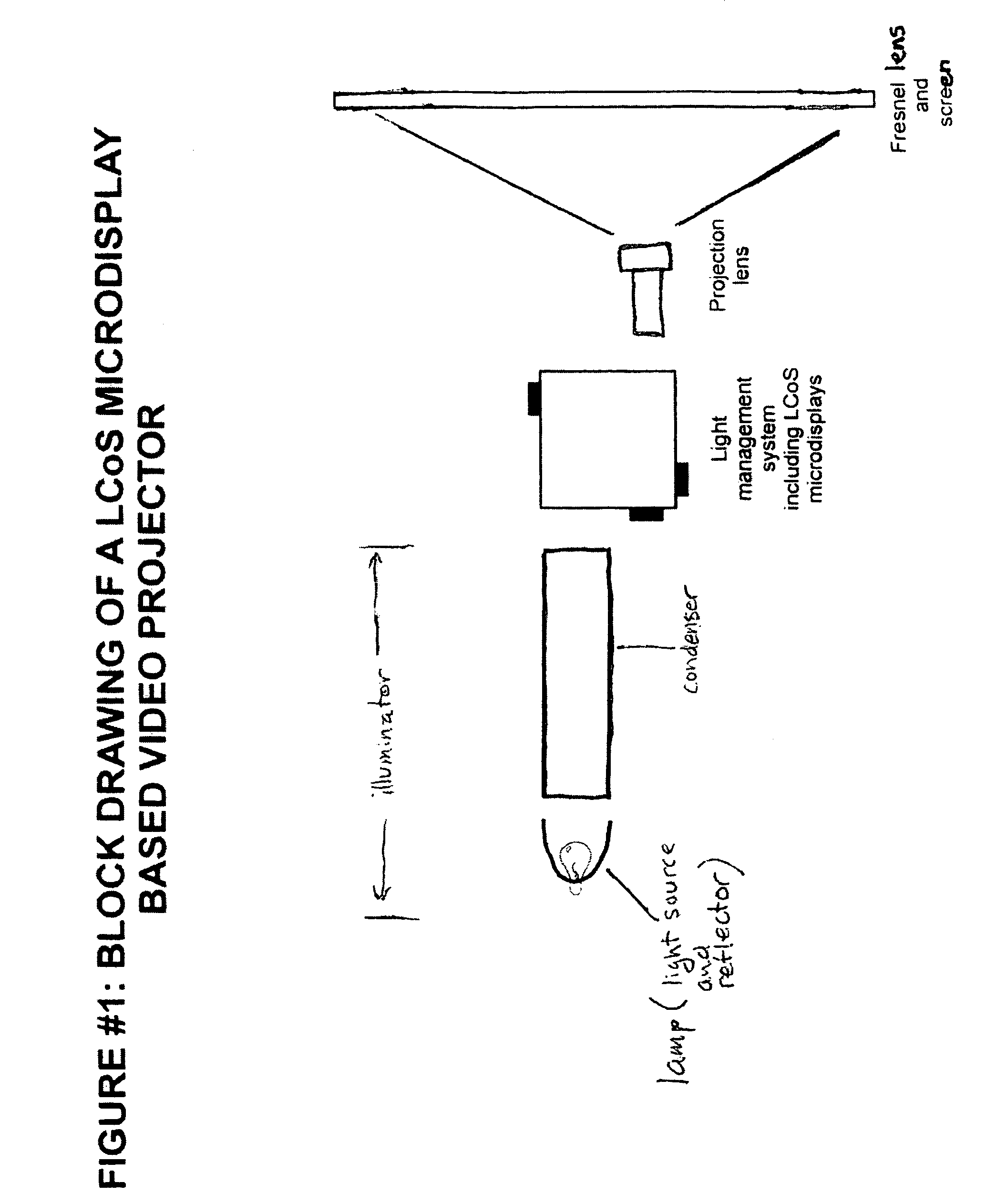
[0026]The invention disclosed in this document is an illuminator configured to output linearly polarized light. The disclosed illuminator is compact, inexpensive, highly efficient, and is well suited for light management systems, particularly for use in projection televisions and other applications.

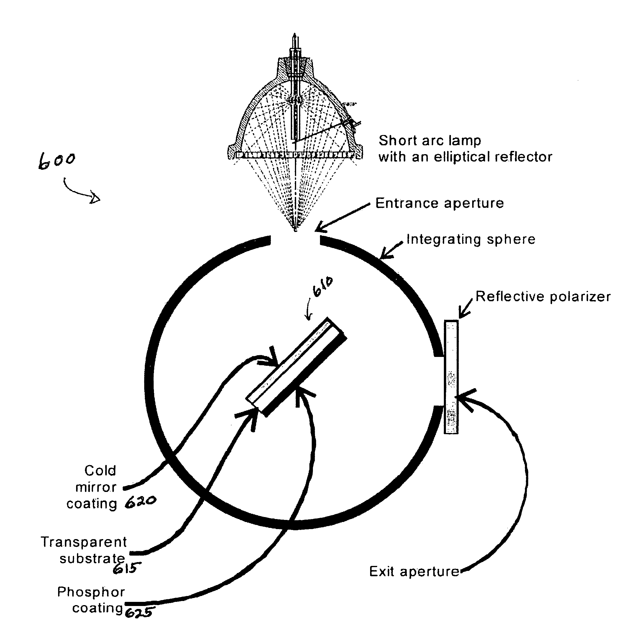
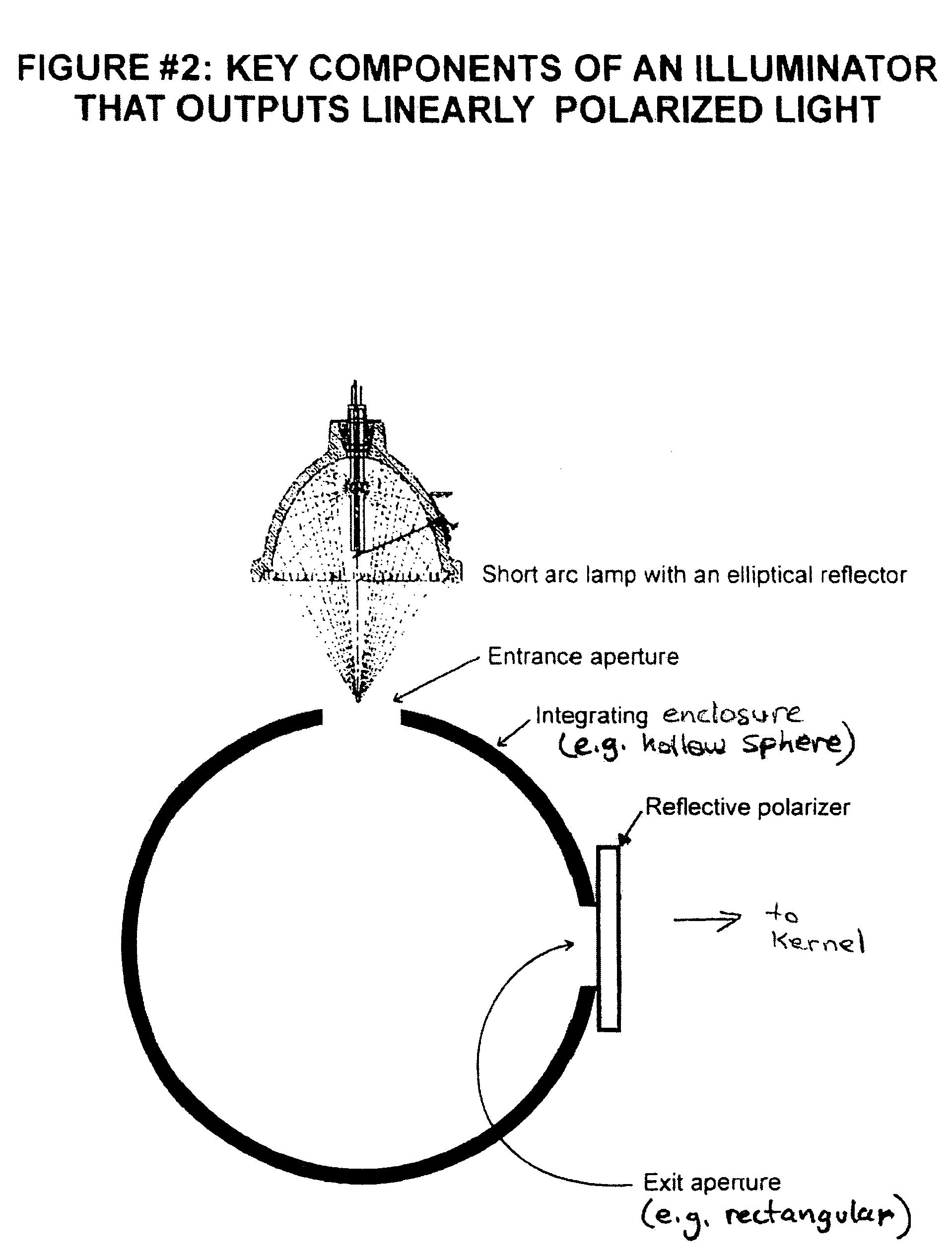
[0027]The basic configuration of the illuminator is illustrated in FIG. 2. As shown, the light source is a short arc lamp with an elliptical reflector. The non-homogeneous, unpolarized light produced by the lamp is focused through a small entrance aperture in the wall of an integrating sphere. Once in the sphere, the light beam is scattered by impact with the interior wall of the sphere. The scattering serves to homogenize the intensity of the light within the sphere. Some of the light eventually encounters the exit aperture.

[0028]A reflective linear polarizer is positioned at the exit aperture. One polarization of light (S for example) is passed by the reflective polarizer and leaves the...


PUM


Abstract

A hollow sphere with a scattering (e.g., white diffusive) interior surface directs light input from at least one input light source to an exit. In one embodiment, an internal hot mirror and phosphor are positioned to intercept the input light on which visible light is reflected and ultraviolet light is directed to the phosphor for conversion to visible light. The exit has a reflective polarizer that passes light of a selected polarization to an output. Light of other polarization(s) is reflected back into the sphere where it becomes unpolarized because of reflections and may eventually be returned to the exit at the selected polarization.

Description

CROSS REFERENCE TO RELATED APPLICATIONS AND CLAIM OF PRIORITY[0001]This invention claims priority to the following co-pending U.S. patent application, which is incorporated herein by reference, in its entirety:[0002]Berman, U.S. patent application Ser. No. 10 / 845,459, entitled “An Illuminator that Outputs Linearly Polarized Light and that is Suitable for use in Microdisplay Based Light Engine Applications,” filed, May 13, 2004.COPYRIGHT NOTICE[0003]A portion of the disclosure of this patent document contains material which is subject to copyright protection. The copyright owner has no objection to the facsimile reproduction by anyone of the patent document or the patent disclosure, as it appears in the Patent and Trademark Office patent file or records, but otherwise reserves all copyright rights whatsoever.BACKGROUND OF THE INVENTION[0004]1. Field of Invention[0005]The invention disclosed in this document is an illuminator that outputs linearly polarized light. More particularly, t...

Claims


Application Information

Patent Timeline
IPC IPC(8): H04N5/74H04N9/31
CPCG02B27/28H04N9/315H04N9/3197G03B21/2073G03B21/2026G03B21/208G01J1/0429G01J1/08G01J2001/0481
Inventor BERMAN, ARTHUR
Owner LIGHTMASTER SYST
Why Eureka
Try Eureka