
Lens module and projector

a technology of projector and lens module, which is applied in the field of lens module, can solve the problems of small projection screen, light interference and electrostatic interference, and the relatively large processor in size is not conducive to the installation in the miniature projector, and achieves the effects of small volume, high precision and digital signal transmission, and light weigh

Active Publication Date: 2018-02-01
CORETRONIC
View PDF2 Cites 4 Cited by
  • Summary
  • Abstract
  • Description
  • Claims
  • Application Information

AI Technical Summary

Benefits of technology

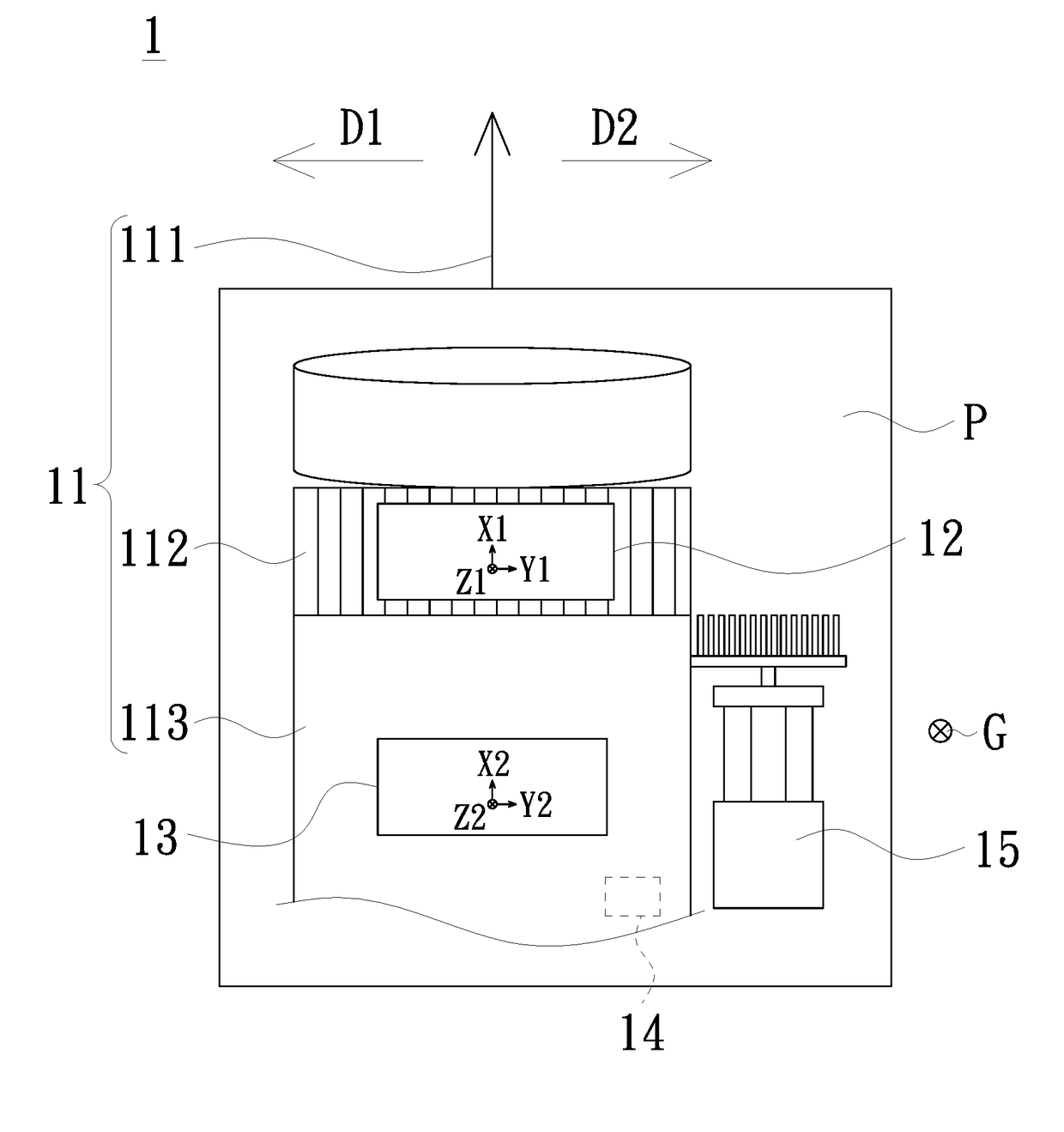
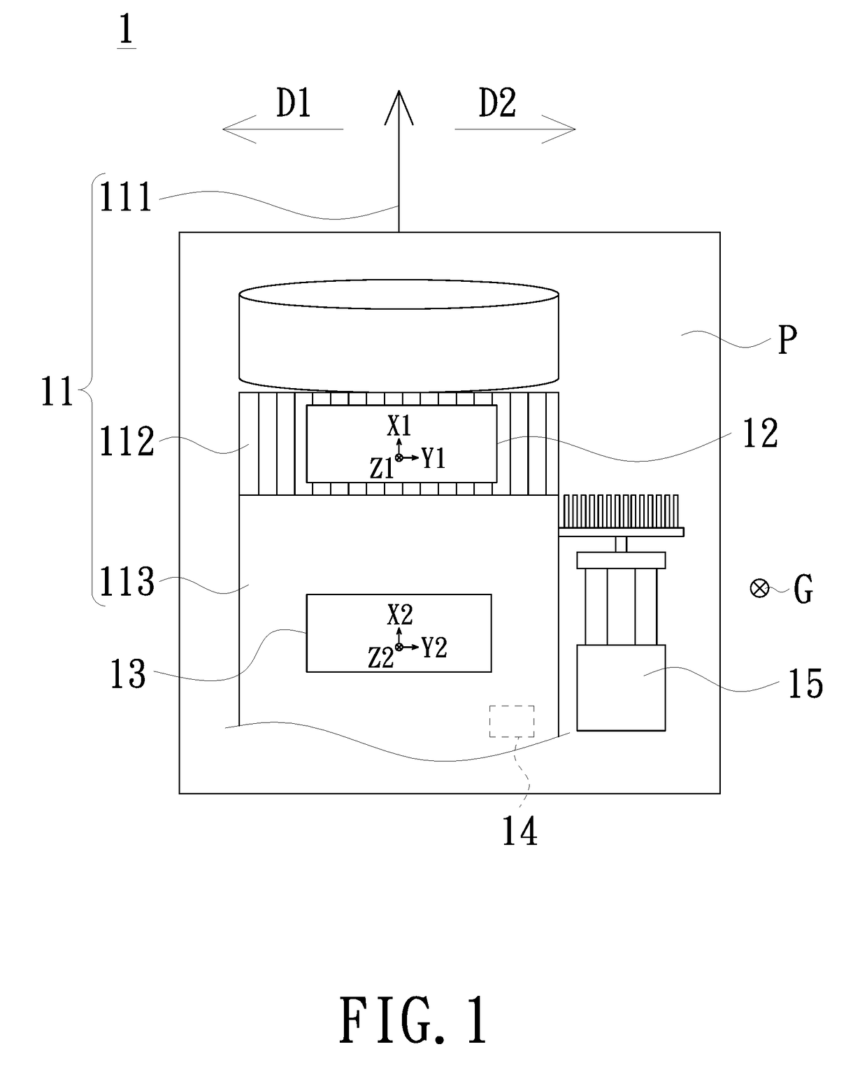
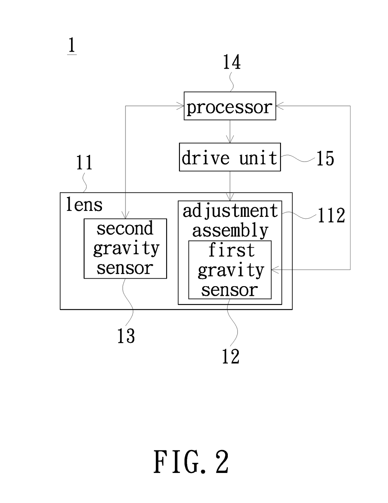
The invention is a lens module that uses a gravity sensor to detect the rotation angle and direction of an adjustment assembly. This sensor provides data to a processor, which controls the focus adjustment of the lens based on the calculated angles. The gravity sensor is small and lightweight, making it suitable for miniature projectors, and it is not affected by light interference. It has high precision and accuracy, and transmits signals in a digital format, which reduces noise. Overall, the invention improves the accuracy and efficiency of focus adjustment in lens modules.

Problems solved by technology

Usually when a projector is use, the size of the projection screen and the distance of the projection screen to the projector may be limited by the environment.
However, the conventional processor has a relatively large size regardless digital sensing or analog sensing is adopted, and the relatively-large processor in size is not conducive to the installation in the miniature projector.
Moreover, to work properly, the photoelectric or capacitive sensor must have a calibration each time when the projector is turned on and the installation of the processor inside the projector may lead to the light interference and electrostatic interference.

Method used


Image

  • Lens module and projector
  • Lens module and projector
  • Lens module and projector

Examples


Embodiment Construction

[0020]In the following detailed description of the preferred embodiments, reference is made to the accompanying drawings which form a part hereof, and in which is shown by way of illustration specific embodiments in which the invention may be practiced. In this regard, directional terminology, such as “top”, “bottom”, “front”, “back”, etc., is used with reference to the orientation of the Figure(s) being described. The components of the invention can be positioned in a number of different orientations. As such, the directional terminology is used for purposes of illustration and is in no way limiting. On the other hand, the drawings are only schematic and the sizes of components may be exaggerated for clarity. It is to be understood that other embodiments may be utilized and structural changes may be made without departing from the scope of the invention. Also, it is to be understood that the phraseology and terminology used herein are for the purpose of description and should not b...


PUM


Abstract

A lens module includes a lens, a first gravity sensor and a processor. The lens includes an optical axis and an adjustment assembly. The adjustment assembly rotates around the optical axis. The first gravity sensor is disposed on the adjustment assembly. The adjustment assembly drives the first gravity sensor to rotate. The first gravity sensor is configured to perform detection at different time points. The first gravity sensor generates a first output at a first time point and a second output at a second time point. The processor calculates first and second angles of the first gravity sensor relative to a water level according to the first and second outputs respectively. The processor controls a focus adjustment of the lens according to the first angle and the second angle. A projector employing the aforementioned lens module is also provided.

Description

CROSS-REFERENCE TO RELATED APPLICATION[0001]This application claims the priority benefit of CN201610602058.2 field on 2016 / 07 / 28. The entirety of the above-mentioned patent application is hereby incorporated by reference herein and made a part of this specification.FIELD OF THE INVENTION[0002]The invention relates to a lens module, and more particularly to a lens module for a projector.BACKGROUND OF THE INVENTION[0003]Projector is a display device for producing a large-size screen. The imaging principle of a projector is converting an illumination beam generated by a light source into an image beam by a light valve and projecting the image beam onto a projection screen or a wall through a lens thereby displaying images. With the progress of projection technology and the reduction of manufacturing cost, the application of projector gradually expands from the commercial use to the domestic use, and therefore, the miniature projector having relatively small size and light weight has gr...

Claims


Application Information

Patent Timeline
Patent Type & Authority Applications(United States)
IPC IPC(8): G03B21/53G01V7/02G03B21/14
CPCG03B21/53G01V7/02G03B21/142H04N9/315
Inventor KE, CHI-WENLIN, HUNG-WEILIN, HUI-JU
Owner CORETRONIC
Learn More