Transmission mode RFOG and method for detecting rotation with RFOG

a technology of rotational sensor and transmission mode, applied in the field of gyro systems, can solve the problems of affecting the observed shape of the resonance dip, reducing the accuracy of the rotational rate measurement, and errors in the detection of the resonance center

Active Publication Date: 2008-02-05
HONEYWELL INT INC
View PDF11 Cites 46 Cited by
  • Summary
  • Abstract
  • Description
  • Claims
  • Application Information

AI Technical Summary

Problems solved by technology

The RFOG may encounter a variety of anomalies that decrease the accuracy of the rotational rate measurement.
Non-resonant, stray undesired light (e.g., light that is not properly matched in the polarization mode or the spatial mode of the resonator) may interfere with the light in the matched state that is reflected by the resonator and circulated in the resonator and, thus, produce errors in the detection of the resonance centers.
Although the residual launch light component may not resonate in the resonator when the desired light component is near resonance, this residual light may adversely affect the observed shape of the resonance dip resulting from the desired light component.
Interference from non-mode matched residual light in the launch condition having either the undesired polarization state or higher order spatial mode components of the resonator may complicate identification of the resonance centers and provide inaccurate determinations of resonance frequencies and rotations rates.
Determination of the resonance centers for each of the resonance frequencies of the CW and CCW beams directly affects the rotational rate measurement and, thereby severely limits the accuracy of the RFOG.
This may be exacerbated by possible variances in the states of polarization of the fiber inside the resonator due to temperature or stress variation, thereby making repeated light launches into one polarization state of the resonator more difficult.
Polarization-induced errors may severely limit the accuracy of the RFOG because the accuracy of the determination of the resonance centers, and thus the resonance frequencies in the CW and CCW directions, directly affects the rotational rate measurement.
Additionally, these errors in the measurement may change radically with respect to the temperature in conventional optical fibers due to the sensitivity of the associated birefringence to temperature.

Method used


Image

  • Transmission mode RFOG and method for detecting rotation with RFOG
  • Transmission mode RFOG and method for detecting rotation with RFOG
  • Transmission mode RFOG and method for detecting rotation with RFOG

Examples


Embodiment Construction

[0019]The following detailed description of the invention is merely exemplary in nature and is not intended to limit the invention or the application and uses of the invention. Furthermore, there is no intention to be bound by any theory presented in the preceding background of the invention or the following detailed description of the invention.

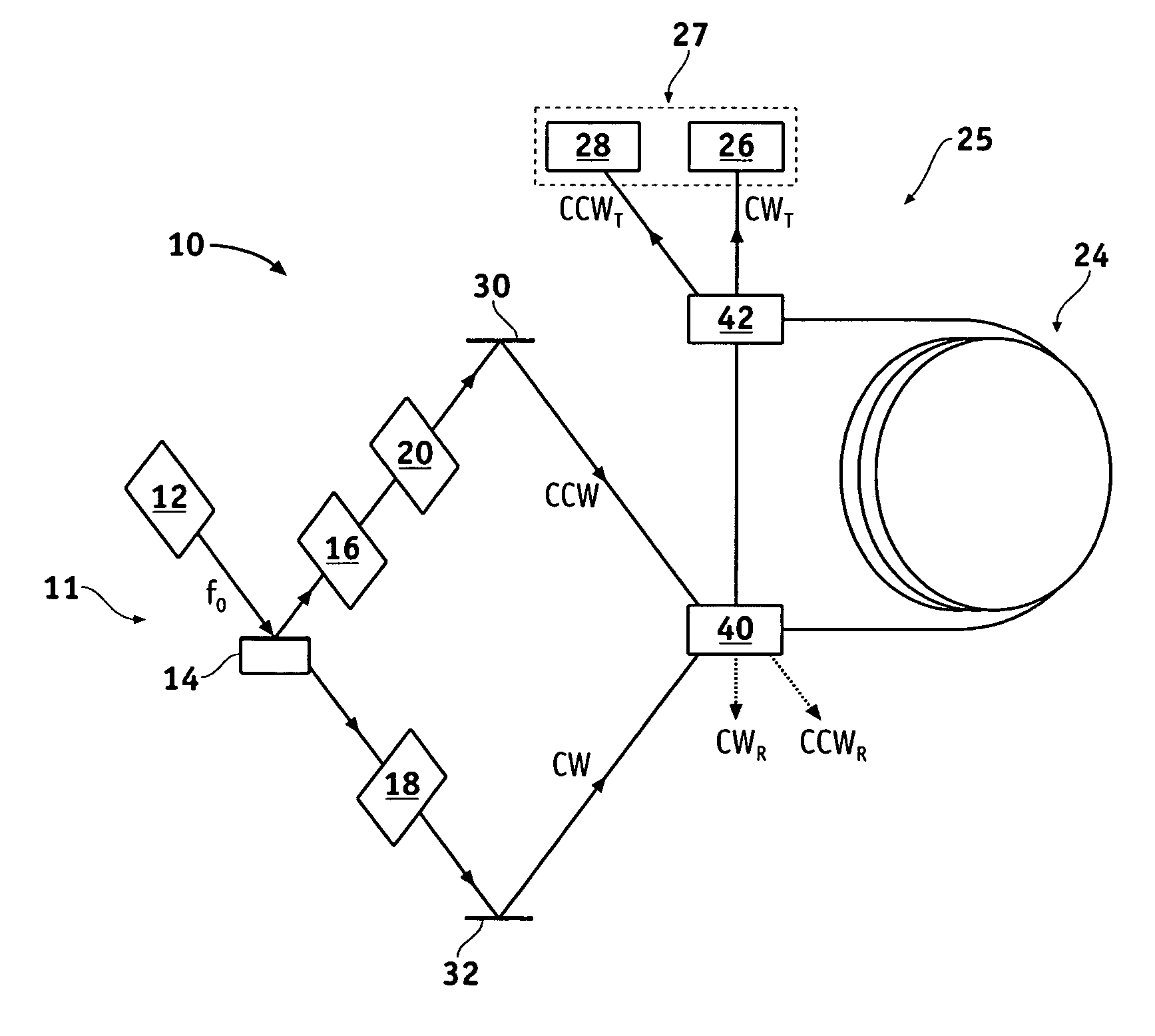
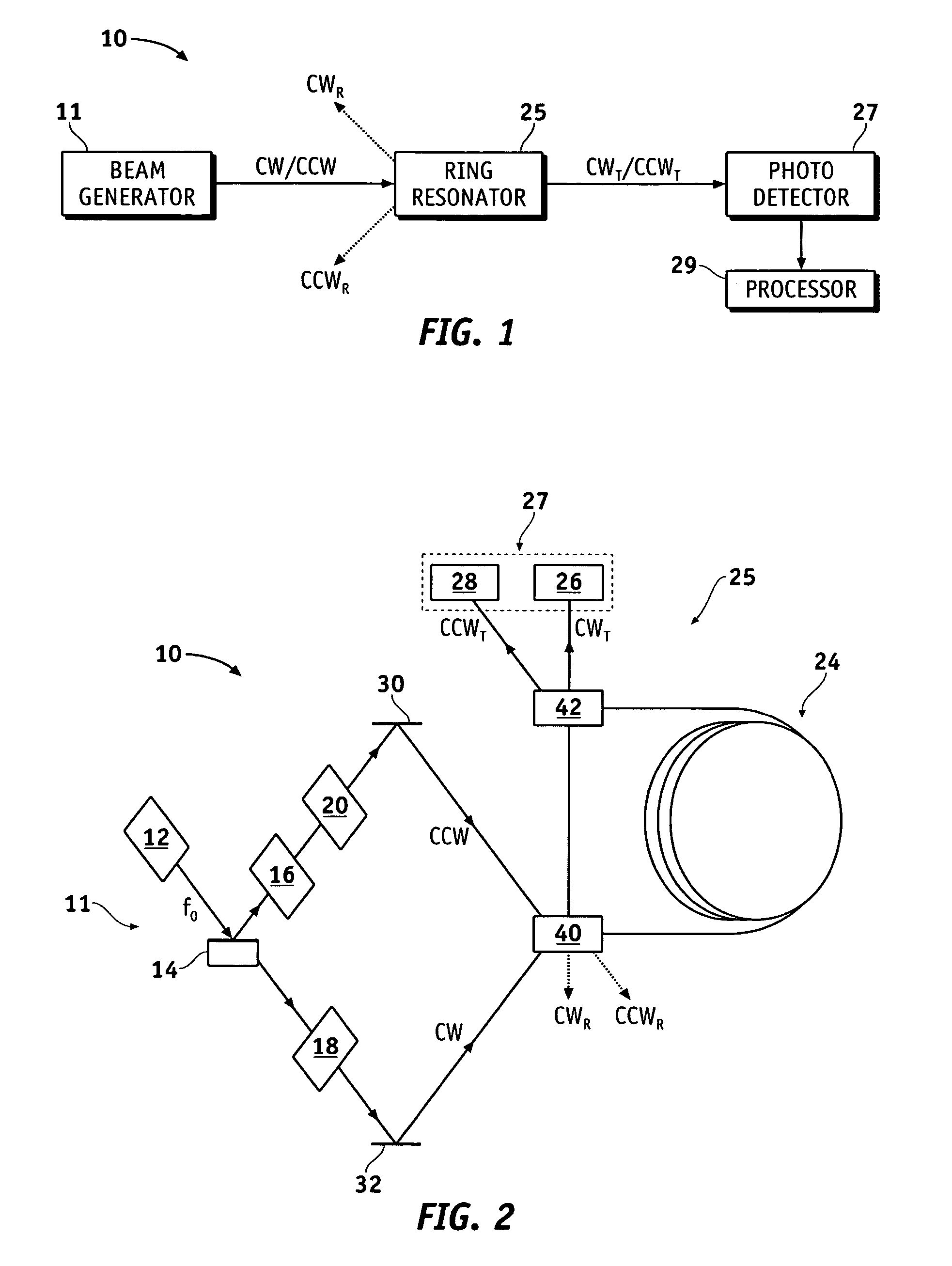
[0020]Referring now to the drawings, FIG. 1 is a block diagram of a resonator fiber optic gyro (RFOG) 10 in accordance with an exemplary embodiment of the present invention. The RFOG 10 comprises a beam generator 11 configured to generate input light beams (e.g., a clockwise (CW) input light beam and a counter-clockwise (CCW) input light beam), a ring resonator 25 having an input for receiving the input light beams and having an output, a photodetector 27, and a processor 29 coupled to the photodetector 27. The ring resonator 25 receives the CW and CCW input light beams at the input, circulates a portion of these input light beams, and produ...


PUM


Abstract

Methods and apparatus are provided for sensing a rotation rate of a ring resonator in a transmission mode. A ring resonator for circulating light beams in counter-propagating directions comprises an optical fiber coil having a hollow core and first and second ends. A first optical element is configured to receive an input light beam and direct a portion of the input light beam in a counter-propagating direction of the ring resonator. A second optical element is configured to direct with the first optical element a majority of a circulating light beam in the counter-propagating direction of the ring resonator and derive a transmission mode component of the circulating light beam at one of the ends. The portion of the input light beam enters one of the first and second ends. The circulating light beam is based on the input light beam. The transmission mode component indicates a resonance peak of the counter-propagating direction of the ring resonator.

Description

FIELD OF THE INVENTION[0001]The present invention generally relates to gyro systems, and more particularly relates to rotational sensor techniques for use in a fiber optic gyroBACKGROUND OF THE INVENTION[0002]Gyros have been used to measure rotation rates or changes in angular velocity about an axis. A basic conventional fiber optic gyro (FOG) includes a light source, a beam generating device, and a coil of optical fiber coupled to the beam generating device that encircles an area. The beam generating device transmits light beams into the coil that propagate in a clockwise (CW) direction and a counter-clockwise (CCW) direction along the core of the optical fiber. Many FOGs utilize glass-based optical fibers that conduct light along a solid glass core of the fiber. The two counter-propagating (e.g., CW and CCW) beams experience different pathlengths while propagating around a rotating path, and the difference in the two pathlengths is proportional to the rotational rate.[0003]In a re...

Claims


Application Information

Patent Timeline
Patent Type & Authority Patents(United States)
IPC IPC(8): G01C19/72
CPCG01C19/727
Inventor SANDERS, GLEN A.STRANDJORD, LEE K.
Owner HONEYWELL INT INC
Why Eureka
Try Eureka