Plasma-jet spark plug and ignition system

a technology of spark plugs and spark plugs, applied in spark plugs, instruments, machines/engines, etc., can solve problems such as deterioration of durability of spark plugs

Inactive Publication Date: 2008-02-12
NGK SPARK PLUG CO LTD
View PDF6 Cites 36 Cited by
  • Summary
  • Abstract
  • Description
  • Claims
  • Application Information

AI Technical Summary

Benefits of technology

[0006]It is therefore an object of the present invention to provide a plasma-jet spark plug capable of generating a plasma flame assuredly even by a relatively low energy supply.

Problems solved by technology

However, the center and ground electrode get consumed heavily by such a high energy supply so that the spark plug deteriorates in durability.

Method used


Image

  • Plasma-jet spark plug and ignition system
  • Plasma-jet spark plug and ignition system
  • Plasma-jet spark plug and ignition system

Examples


experiment 1

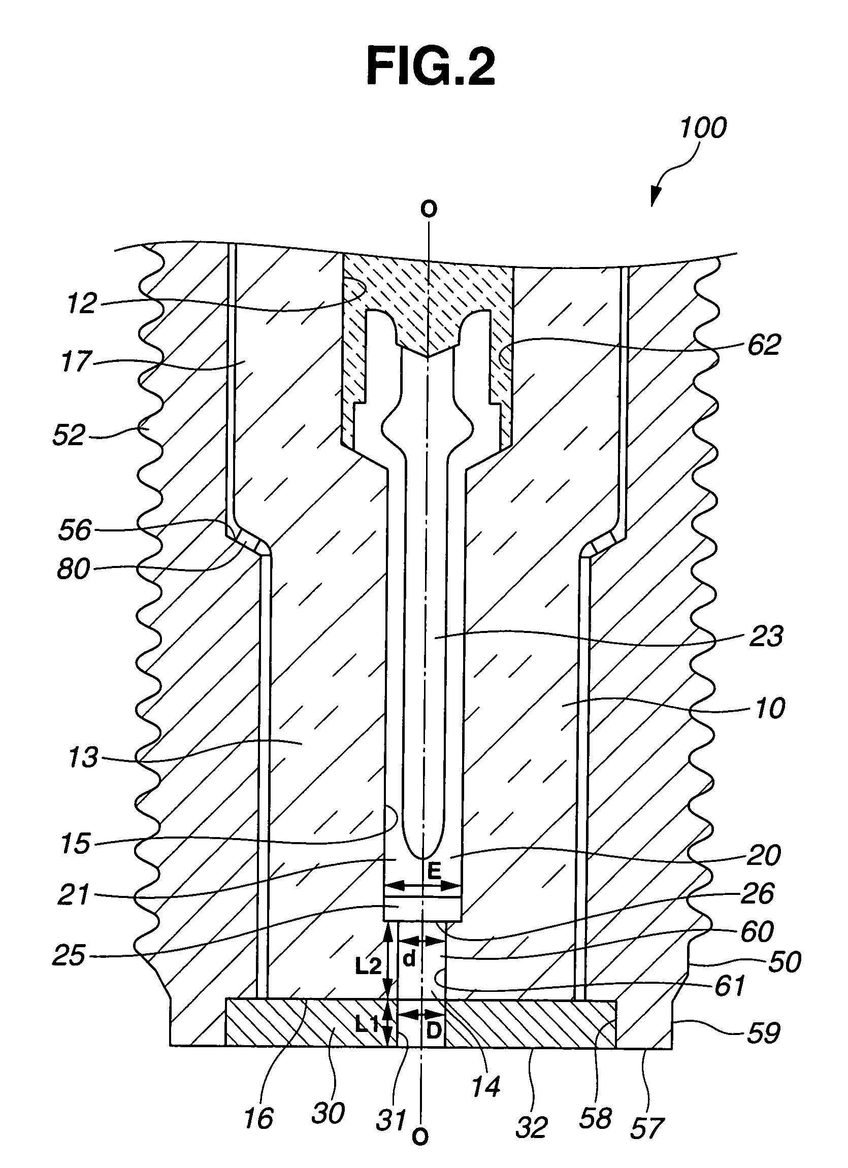
[0041]Test samples (sample numbers 1-1 and 1-2) of the spark plug 100 and test samples (sample numbers 1-3 and 1-4) of comparative spark plugs were produced under the same conditions except for their dimensions. The dimensions of the test samples are indicated in TABLE 1. Using the power supply unit 200 having a capacity to supply 200 mJ of energy for one discharge shot, each of the test samples was activated to eject a plasma. The length of the plasma ejected from the front end face 32 of the ground electrode 30 was determined by image observation. The test sample was judged to have succeeded in plasma flame discharge and rated as “O” when the plasma ejection length was 2 mm or larger. When the plasma ejection length was smaller than 2 mm, the test sample was judged to have failed in plasma flame discharge and rated as “X”. The test results are indicated in TABLE 1.

[0042]

TABLE 1PlasmaSampleDL1dL2L1 + L2flameNo.(mm)(mm)(mm)(mm)(mm)discharge1-10.80.80.81.72.5d = D◯1-20.81.50.83.55.0d...

experiment 2

[0043]Test samples (sample numbers 2-1 and 2-2) of the spark plug 100 and test sample (sample number 2-3) of comparative sample plug were produced under the same conditions except for their dimensions. The dimensions of the test samples are indicated in TABLE 2. Using the power supply unit 200 having a capacity to supply 160 mJ of energy for one discharge shot, each of the test samples was activated to eject a plasma. The ejection length of the plasma was determined by image observation to judge whether the test sample succeeded or failed in plasma flame discharge in the same manner as in Experiment 1. Further, each of the test samples was tested for its ignition limit air-fuel ratio by mounting the test sample on a 2000 cc six-cylinder engine, driving the engine at 2000 rpm and activating the test sample to cause ignition at different air-fuel ratios. The ignition limit air-fuel ratio of the test sample was determined as the air-fuel ratio value at the time the frequency of occurre...

experiment 3

[0045]A test sample of the spark plug 100 was produced with the following dimensions: D=1.0 mm, L1=1.0 mm, d=0.5 mm and L2=2.0 mm and subjected to ignitability test. The ignitability test was herein conducted by mounting the test sample in a pressure chamber, charging the chamber with a mixture of air and C3H8 fuel gas (air-fuel ratio: 22) to a pressure of 0.05 MPa, activating the test sample by means of the power supply unit 200 and monitoring the pressure in the chamber with a pressure sensor to judge the success or failure of ignition of the air-fuel mixture. The output of the power supply unit 200 was varied from 30 to 70 mJ by using various power coils. The ignition probability of the test sample was determined by performing the above series of process steps 100 times at each energy level. The test results are indicated in FIG. 5. The test sample failed to cause ignition by the energy supply of 30 mJ and had an ignition probability of about 65% by the energy supply of 40 mJ. Ho...


PUM


Abstract

A plasma-jet spark plug includes a metal shell, an electrical insulator retained in the metal shell, a center electrode held in an axial hole of the electrical insulator to define a cavity by a front end face of the center electrode and an inner circumferential surface of the insulator axial hole and a ground electrode fitted to a front end face of the electrical insulator and formed with an opening for communication between the cavity and the outside of the spark plug and satisfies the following dimensional relationships:d≦D≦3d;0.5 mm≦d≦1.5 mm;L1≦1.5 mm;2d≦L2≦3.5 mm; andL2+{(D−d) / 2}≦3.5 mmwhere D is a diameter of the ground electrode opening; L1 is a thickness of the ground electrode; d is a diameter of the cavity; and L2 is a depth of the cavity.

Description

BACKGROUND OF THE INVENTION[0001]The present invention relates to a plasma-jet spark plug that produces a plasma by a spark discharge to ignite an air-fuel mixture in an internal combustion engine. The present invention also relates to an ignition system using the plasma-jet spark plug.[0002]A spark plug is widely used in an automotive internal combustion engine to ignite an air-fuel mixture by a spark discharge. In response to the recent demand for high engine output and fuel efficiency, it is desired that the spark plug increase in ignitability to show a higher ignition-limit air-fuel ratio and achieve proper lean mixture ignition and quick combustion.[0003]Japanese Laid-Open Patent Publication No. 2-72577 discloses, as one example of high-ignitability spark plug, a plasma-jet spark plug that has a pair of center and ground electrodes defining therebetween a discharge gap and an electrical insulator surrounding the discharge gap so as to form a discharge cavity within the discharg...

Claims


Application Information

Patent Timeline
Patent Type & Authority Patents(United States)
IPC IPC(8): F02B23/04G01P3/66
CPCF02P9/007H01T13/50H01T13/52
Inventor HAGIWARA, KATSUNORINAGASAWA, SATOSHIMATUTANI, WATARU
Owner NGK SPARK PLUG CO LTD
Why Eureka
Try Eureka